2001 Jaguar Vanden Plas Cold and warm air

Tiny
NICOLO
  • MEMBER
  • 2001 JAGUAR VANDEN PLAS
  • V8
  • 2WD
  • AUTOMATIC
  • 12,000 MILES
I am getting cold air from the center part of the vents on the dash board, warm air from the sides of the same vent, and warm air on the bottom ( feet) vents! This with the temperature set at the lowest, if I put the temperature up a few degrees I get warm air everywhere, and it gets hot inside.
I had the frion checked and it is OK
What could be a valve stuck? Some tem. Probe defective?
The problem started suddenly, at one point went back to funcioning properly, that the problem started again.
Any suggestions?
Thank you.
Wednesday, February 18th, 2009 AT 7:10 PM

14 Replies

Tiny
DAVE H
  • MECHANIC
  • 13,383 POSTS
Hello .. thanks for the donation .. much appreciated

The HVAC system has a self-diagnostic system which should tell you where the actual fault lies .. hope this helps ... let me know if you require more information or assistance !

SELF-DIAGNOSTICS
NOTE:Specific circuit and component testing procedures are not available. Manufacturer recommends using Portable Diagnostic Unit (PDU) for circuit and component fault diagnosis.

A/C-heater control panel contains a self-diagnostic function. A/C-heater control panel can store up to 5 A/CCM trouble codes at a time. When a system fault occurs, A/CCM stores information about the event in memory. Upon next ignition cycle, a beep will be heard and ER (error) will be displayed for 5 seconds on A/C-heater control panel.
RETRIEVING DIAGNOSTIC TROUBLE CODES
NOTE:Diagnostic Trouble Codes (DTC) can be retrieved using Jaguar Portable Diagnostic Unit (PDU) or a scan tool. If not available, A/C-heater control panel DTCs can be retrieved using on-board diagnosis incorporated in A/CCM. PDU diagnosis is more comprehensive than A/C-heater control panel diagnosis.

System Self-Diagnostic Test
A/C-heater control panel display will flash repeatedly indicating a list of 2-digit numbers. See DIAGNOSTIC TROUBLE CODE DEFINITIONS table. This procedure must be completed in order, through one complete cycle:
Display Element Check

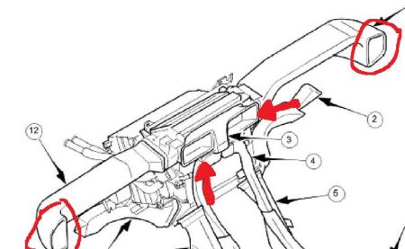
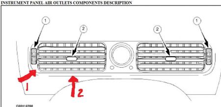
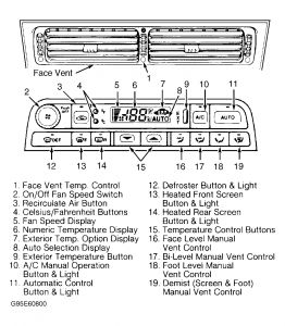
Turn ignition switch to OFF position. Simultaneously press and hold AUTO and RECIRC buttons. See Fig. 1 . Turn ignition switch to ON position while holding buttons. All display elements should illuminate and segments will flash on and off. If any display elements or segments do not light, an A/C-heater control panel or light fault is indicated.
Display Stored Numeric Trouble Code(s)
(1)


https://www.2carpros.com/forum/automotive_pictures/266999_1_12.jpg


Press AUTO button. A 2-digit trouble code will be displayed. Codes 11, 15 and 21, will cause audible beep and ER to be displayed. If zero appears, there are no stored trouble codes, wait 30 seconds to allow system self-test to finish. A trouble code followed by a beep indicates an active trouble code. A trouble code not followed by a beep indicates an inactive trouble code stored in memory.
Scroll Through Trouble Code(s)

Press face button to display stored trouble codes. A maximum of 5 trouble codes can be stored.
Clear Stored Trouble Code(s)

Simultaneously press face and "R" (heated rear screen) buttons. It may be necessary to press face and "R" buttons to clear each stored trouble code.
NOTE:Actuator codes are not system trouble codes. See ACTUATOR CHECK under TROUBLE SHOOTING.

Initiate Actuator Check
Press RECIRC button to initiate actuator check. Actuator codes 20 through 27. Press fan to skip actuator check.
Exit System Self-Diagnostic Test

Press fan button to exit system self-diagnostic test. Press PUSH OFF button to restore normal operation.

DIAGNOSTIC TROUBLE CODE DEFINITIONS
DTC ...(Panel DTC)...Component
..(0)......................(1) Normal Operation
P0335 ..(.....)......... Engine Speed Input
B1250... (11) .........In-Vehicle Temperature Sensor
B1253... (11)......... In-Vehicle Temperature Sensor
B1254... (12)......... Ambient Temperature Sensor
B1257 ...(12) .........Ambient Temperature Sensor
B1258... (21)......... Solar Sensor
B1260 ...(21)......... Solar Sensor
B1262... (44) ........(2) Defrost Servo Motor
B1263... (45) ........(2) Center Vent Servo Motor
B1264 ...(46) ........(2) Foot Servo Motor
B1265... (43)........ (2) Cool Air By-Pass Servo Motor
B1266... (41) ........(2) Left Fresh/Recirculated Air
.................................Servo Motor
B1267... (42)........ (2) Right Fresh/Recirculated Air
................................ Servo Motor
B1268... (34)......... (3) Defrost Vent Feedback ....................Potentiometer
B1271... (34) .........(3) Defrost Vent Feedback
..................................Potentiometer
B1272... (35).......... (3) Center Vent Feedback
.................................. Potentiometer
B1275 ...(35).......... (3) Center Vent Feedback
...................................Potentiometer
B1276 ...(36) ...........(3) Foot Vent Feedback
....................................Potentiometer
B1279... (36) ...........(3) Foot Vent Feedback
....................................Potentiometer
B1280... (33) ...........(3) Cool Air By-Pass Feedback
................................... Potentiometer
B1283... (33)........... (3) Cool Air By-Pass Feedback
................................... Potentiometer
B1284.... (31).......... (3) Left Fresh/Recirculated Air
................................... Feedback Potentiometer
B1287 ....(31) ...........(3) Left Fresh/Recirculated Air
.................................... Feedback Potentiometer
B1288.... (32) ...........(3)Right Fresh/Recirculated Air
................................... Feedback Potentiometer
B1291.... (32)........... (3) Right Fresh/Recirculated
..................................Air Feedback Potentiometer
B1292.... (.....)............. Battery Voltage Supply
.................................. Through A/C Isolate Relay
B1294.... (.....) .............Battery Voltage Supply
...................................Through A/C Isolate Relay
B1297.... (.....) ......Sensor 5-Volt Reference Voltage
B1298.... (.....)...... Sensor 5-Volt Reference Voltage
B1299.... (.....) ......Sensor 5-Volt Reference Voltage
B1355.... (.....)...... Battery Voltage Supply
B1849..... (24) ......Face Vent Differential
.............................Temperature Control
B1852..... (24) ......Face Vent Differential
........................... Temperature Control
B1853.... (.....)...... Aspirator Motor
B1856.... (.....) ......Aspirator Motor
B1857 ....(.....)...... Ignition Switched (AUX/ON)
........................... Ground Signal
B1858..... (23)..... (4) Refrigerant Dual Pressure
................................Switch
B1861..... (23)..... (4) Refrigerant Dual Pressure
................................Switch
B1862 .....(22) ...........Compressor Lock Signal
B1863 ....(.....) ...........Sensor Signal Ground
B1946..... (13)........... Evaporator Temperature
................................ Sensor
B1947..... (13)...... Evaporator Temperature Sensor
B1948...... (14)...... Coolant Temperature Sensor
........................... Signal
B1949 .....(14)....... Coolant Temperature Sensor
............................... Signal
B1966 .....(15)........ Heater Matrix Temperature
.............................. Sensor
B1967..... (15)........ Heater Matrix Temperature
............................. Sensor
B1968 .....(.....) ......Heater Pump
B1969..... (.....)...... Compressor Clutch Circuit
U1263..... (.....)....... Control Panel Serial
............................. Communication
U1264..... (.....)....... Control Panel Serial
..............................Communication
(1)When there are no DTCs, WAIT 30 seconds for system self-diagnostic test to finish.
(2)Check for an open or short in motor drive circuit, or a sticking/jammed motor flap.
(3)Open or short in potentiometer feed circuit. At times, motor may overrun and set additional codes. Cycling ignition on and off 2 or 3 times may correct problem.
(4)Temperatures less than 32 °F (0 °C) may set false trouble code due to low refrigerant pressure. Temperatures greater than 95 °F (35 °C) may set false trouble code due to temporary high refrigerant pressure.

Repair faults before clearing DTC's

CLEARING DIAGNOSTIC TROUBLE CODES
To clear trouble codes, turn ignition to ON position. Simultaneously press face and "R" (heated rear screen) buttons. It may be necessary to press face and "R" buttons to clear each stored trouble code. Press fan button to exit system self-diagnostic test. Press PUSH OFF button to restore normal operation. See Fig. 1 .
Was this
answer
helpful?
Yes
No
Wednesday, February 18th, 2009 AT 9:22 PM
Tiny
NICOLO
  • MEMBER
  • 11 POSTS
Hi I did the test and I got code 23, but I do not remember any beep, how can I check further if indeed it is the refrigerant dual pressure switch and were is it located?
Much apreciated
Nicolo
Was this
answer
helpful?
Yes
No
Wednesday, February 18th, 2009 AT 10:50 PM
Tiny
DAVE H
  • MECHANIC
  • 13,383 POSTS
Remember the code (write it down) clear the code as it say's it is innactive. Test the system. And recheck for codes to see if it returns or you get any more codes?

DTC B1858 (23): REFRIGERANT DUAL PRESSURE SWITCH
Fault Description
Refrigerant dual pressure switch circuit failure.
Possible Cause
Check system refrigerant charge. Check refrigerant dual pressure switch circuit for an open, high resistance or a short to battery voltage. Check for high engine temperature in high ambient air temperatures. See WIRING DIAGRAMS. Repair or replace as necessary.
Was this
answer
helpful?
Yes
No
Wednesday, February 18th, 2009 AT 11:15 PM
Tiny
NICOLO
  • MEMBER
  • 11 POSTS
Hello again, I cleared the code, went for a drive about 2 hours, the code did not come back, now I get 0, but the problem persists.

I had a shop check the refrigerant it is OK engine temperature it is fine ambient temperature is about 20-24 Celcius.
Any other suggestion? Should I check anything also on top of the dual pressure switch?
Thanks, Nicolo
Was this
answer
helpful?
Yes
No
Thursday, February 19th, 2009 AT 12:03 AM
Tiny
DAVE H
  • MECHANIC
  • 13,383 POSTS
Hello

Let me just check I am understanding your fault correctly .. you are getting a mixture of warm and cold air from the same vents marked with red arrows ..where my #1 arrow is you are getting warm air and where my #2 arrow is you are getting cold air with the temp set at it's lowest ? What about the side vent's (circled) .. also have you cleaned or replaced the air/pollen filters recently at the bottom of the windscreen (outside)


https://www.2carpros.com/forum/automotive_pictures/266999_vent2_1.jpg


https://www.2carpros.com/forum/automotive_pictures/266999_vent_1.jpg

Was this
answer
helpful?
Yes
No
Thursday, February 19th, 2009 AT 6:59 AM
Tiny
NICOLO
  • MEMBER
  • 11 POSTS
Hi
I am getting cold and warm from the same center vents, has you have marked, the part near the clock, cold the other half, warm, (for both vents on each side of the clock) this for both certer vents.
The side vents are warm, the foot vents VERY warm.
I am not sure my model has a pollen filter, if it does has never been serviced. (PS the temperature must be set at LOW to get any cold air)

I have taken the cover near the windshield off, the a/c hose going in, the hose with the valve to hook-up the refrigerant test machine gets very cold, I assume the pump etc. Are working properly.
Thanks
Nicolo
Was this
answer
helpful?
Yes
No
Thursday, February 19th, 2009 AT 10:05 AM
Tiny
NICOLO
  • MEMBER
  • 11 POSTS
Answer, please. I need to solve this problem
Was this
answer
helpful?
Yes
No
Thursday, February 19th, 2009 AT 11:20 PM
Tiny
DAVE H
  • MECHANIC
  • 13,383 POSTS
I realise you have made a donation and I am Sorry I didn't get back to you as soon as you would like. But I do have a home/family life as well. And have to research into the possible causes of your fault which is quite a different kind of fault from the norm ! There is no need to be rude? You will need to check the water valve assembly as this should be fully closed when the controls are set to minimum !

Water Valve Assembly
Location
The water valve assembly is located above the water pump, in the engine compartment and is secured to the firewall by a bracket. The valve operates by means of an electrical solenoid which oscillates the valve system between the inlet and outlet ports.
When in automatic mode, the water valve duty cycle is influenced by the following inputs to the A/CCM:
Outlet air temperature
'Air off' heater matrix temperature
External ambient
Coolant temperature
Engine speed (valve closed with the engine not running)
Demand (set) temperature
In-car temperature sensor
Solar sensor
Re-heating of the refrigerated air is controlled by the time that the water valve is open (i.E. Not energized) over a six second interval. The duty cycle of the water valve, the time open / time closed, is controlled by the A/CCM.
Maximum heating demand will cause the water valve to be fully open (not energized) to allow maximum coolant flow through the heater matrix.
At Maximum cooling, the water valve will be fully closed (energized) to prevent hot (engine temperature) coolant entering the heater circuit; the pump however will continue to circulate coolant through both the heater matrix and water valve bypass.
The water valve defaults open when the ignition is OFF.
Under engine stall conditions, when ignition is ON, the water valve will be open.
Was this
answer
helpful?
Yes
No
Friday, February 20th, 2009 AT 6:38 AM
Tiny
NICOLO
  • MEMBER
  • 11 POSTS
Sorry I did not meaqn to be rude, but here in Arizona is getting hot.

A strange thing happened this morning, the system worked perfectly!( I am not sure if this will help analyze the problem) I am not sure if this will last, So I like to be prepared for the next round.
Are you suggesting to go trough the varius settings, sequences and try to find if the fault is the solenoid, the valve, or not signal going troughfrom sensors etc?
Thank you, if I get to the bottom of this I will really apreciate it.
Nicolo
Was this
answer
helpful?
Yes
No
Friday, February 20th, 2009 AT 9:48 AM
Tiny
DAVE H
  • MECHANIC
  • 13,383 POSTS
I think the valve may not be closing all the way. It should not let ANY hot water through when you have the temp setting ALL the way to LOW. If you have it set all the way to low, the valve should not be influenced by other sensors etc.. It may be that the valve is sticking intermittently. As it now seems to be working correctly again. What is your thought's on this?
Was this
answer
helpful?
Yes
No
Friday, February 20th, 2009 AT 2:18 PM
Tiny
NICOLO
  • MEMBER
  • 11 POSTS
Hi
I tend to agree with you, I did'n have time to try anything and the warm air is back as before.
Would you have a part number for that valve?
I will let you know as soon as possible if the valve was the problem.
Thanks
Nicolo
Was this
answer
helpful?
Yes
No
Friday, February 20th, 2009 AT 5:28 PM
Tiny
NICOLO
  • MEMBER
  • 11 POSTS
Hello
I have been trying to locate the valve and solenoid in question. Could you be specific or better still have a sketch to where is it?
Thanks
Nicolo
Was this
answer
helpful?
Yes
No
Saturday, February 21st, 2009 AT 10:44 AM
Tiny
DAVE H
  • MECHANIC
  • 13,383 POSTS
I do not have a part # listed i'm afraid .. they are located on the firewall in the engine compartment .. this is the best diagram i have !!


https://www.2carpros.com/forum/automotive_pictures/266999_jag_1.jpg

Was this
answer
helpful?
Yes
No
+1
Saturday, February 21st, 2009 AT 4:50 PM
Tiny
NICOLO
  • MEMBER
  • 11 POSTS
OK thank you
I will let you kow
Was this
answer
helpful?
Yes
No
Saturday, February 21st, 2009 AT 8:35 PM

Please login or register to post a reply.

Sponsored links