Good morning,
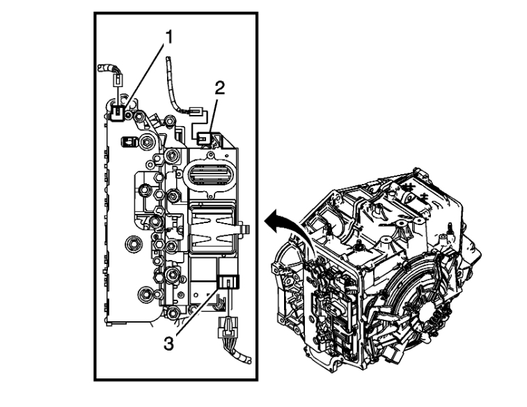
The code is for the clutch pressure solenoid number 4 in the transmission. It is part of the valve body itself. I posted below the flow chart for the code.
Roy
DTC Descriptors
DTC P2714
-
Clutch Pressure Control (PC) Solenoid 4 - Stuck Off
DTC P2715
-
Clutch Pressure Control (PC) Solenoid 4 - Stuck On
Circuit/System Description
The clutch pressure control (PC) solenoid 4 is part of the control solenoid valve assembly which has no serviceable components. The PC solenoid 4 regulates transmission fluid pressure to the 2-6 clutch regulator valve which controls pressure to the 2-6 clutch. The transmission control module (TCM) calculates gear ratio based on the RPM signals from the input speed sensor (ISS) and the output speed sensor (OSS). The TCM compares the expected transmission gear ratio to the calculated gear ratio for each commanded gear.
Conditions for Running the DTC
P2714
DTC P0101, P0102, P0103, P0106, P0107, P0108, P0171, P0172, P0174, P0175, P0201, P0202, P0203, P0204, P0205, P0206, P0207, P0208, P0300, P0301, P0302, P0303, P0304, P0305, P0306, P0307, P0308, P0401, P042E, P0716, P0717, P0722, P0723, or P182E is not set.
Ignition voltage is 8.6 volts or greater.
Output speed is 16 RPM or greater, or throttle position is 0.4 percent or greater.
Throttle position signal is valid.
Engine speed is 400 RPM or greater for 5 seconds.
Transmission fluid temperature is 0°C (32°F) or greater.
High side driver (HSD) is enabled.
P2715
DTC P0101, P0102, P0103, P0106, P0107, P0108, P0171, P0172, P0174, P0175, P0201, P0202, P0203, P0204, P0205, P0206, P0207, P0208, P0300, P0301, P0302, P0303, P0304, P0305, P0306, P0307, P0308, P0401, P042E, P0716, P0717, P0722, P0723, or P182E is not set.
HSD is enabled.
Transmission fluid temperature is 0°C (32°F) or greater.
Commanded and attained range is not 1st gear.
Conditions for Setting the DTC
P2714
TCM has detected an incorrect gear ratio or neutral condition when the 2-6 clutch is commanded ON. This condition must occur 3 times.
P2715
TCM has detected an incorrect gear ratio change when the 2-6 clutch is commanded OFF during a shift or, when 2nd gear ratio is detected in 1st gear. This condition must occur 3 times.
Action Taken When the DTC Sets
P2714
DTC P2714 is a Type A DTC.
TCM commands maximum line pressure.
TCM inhibits Tap Up/Down function.
TCM inhibits manual shifting of forward gears.
TCM freezes transmission adaptive functions.
TCM inhibits neutral idle.
TCM limits the transmission to Reverse and 1st or 3rd gear operation.
P2715
DTC P2715 is a Type A DTC.
TCM commands maximum line pressure.
TCM inhibits neutral idle.
TCM inhibits Tap Up/Down function.
TCM inhibits manual shifting of forward gears.
TCM freezes transmission adaptive functions.
TCM limits the transmission to Reverse and 2nd gear operation.
Conditions for Clearing the DIC/DTC
DTCs P2714 and P2715 are Type A DTCs.
Reference Information
Connector End View Reference
Component Connector End Views
Inline Harness Connector End Views See: Vehicle > Connector Views > X100
Description and Operation
Transmission General Description See: Automatic Transmission/Transaxle > Components > Transmission General Description
Electrical Information Reference
Circuit Testing See: Vehicle > Component Tests and General Diagnostics > Circuit Testing
Connector Repairs See: Vehicle > Component Tests and General Diagnostics > Connector Repairs
Testing for Intermittent Conditions and Poor Connections See: Vehicle > Component Tests and General Diagnostics > Testing for Intermittent Conditions and Poor Connections
Wiring Repairs See: Vehicle > Component Tests and General Diagnostics > Wiring Repairs
DTC Type Reference
Powertrain Diagnostic Trouble Code (DTC) Type Definitions See: A L L Diagnostic Trouble Codes ( DTC ) > Diagnostic Trouble Code Descriptions > Powertrain Diagnostic Trouble Code (DTC) Type Definitions
Scan Tool Reference
Control Module References See: Vehicle > Programming and Relearning for scan tool information
Circuit/System Verification
Warning:
Refer to Parking Brake and Drive Wheels Warning See: Brakes and Traction Control > Technician Safety Information > Parking Brake and Drive Wheels Warning in the Preface section.
Note:
If other DTCs are set, diagnose those DTCs first.
1. Engine idling in Park, with parking brake applied and drive wheels chocked.
2. Verify correct transmission fluid level and condition. Refer to Transmission Fluid Level and Condition Check See: Fluid - A/T > Component Tests and General Diagnostics > Transmission Fluid Level and Condition Check.
3. Verify with a scan tool the TFP Switch 3 parameter values are correct for the Park, Reverse, and Neutral gear selector positions. Refer to Transmission Fluid Pressure Switch Logic See: Automatic Transmission/Transaxle > Mechanical > Transmission Fluid Pressure Switch Logic.
If not the correct values for TFP Switch 3
Refer to Circuit/System Testing below.
If TFP Switch 3 values are correct
4. Place the gear select lever in Drive range. Verify the TFP Switch 3 parameter states are correct for all forward ranges when commanded with a scan tool. Refer to Transmission Fluid Pressure Switch Logic See: Automatic Transmission/Transaxle > Mechanical > Transmission Fluid Pressure Switch Logic.
If not the correct values for TFP Switch 3
Refer to Circuit/System Testing below.
If TFP Switch 3 values are correct
5. Ignition ON, clear the TCM DTCs
6. Perform the Road Test See: Automatic Transmission/Transaxle > Initial Inspection and Diagnostic Overview > Road Test. Verify the transmission operation performs as indicated in the road test instructions and DTC P2714 or P2715 did not set.
If DTC P2714 or P2715 sets
Refer to Circuit/System Testing below.
If DTC P2714 or P2715 did not set
7. After performing the above steps, verify that the DTC does not reset by operating the vehicle within the Conditions for Running the DTC. You may also operate the vehicle within the conditions you observe from the Freeze Frame/Failure Records data. If the vehicle passes the Circuit/System Verification procedure, then STOP. Do not perform the Circuit/System Testing or Component Testing as this may result in an unnecessary part replacement. Refer to Testing for Intermittent Conditions and Poor Connections See: Vehicle > Component Tests and General Diagnostics > Testing for Intermittent Conditions and Poor Connections.
Circuit/System Testing
Note:
You must perform the Circuit/System Verification first.
1. Verify the transmission line pressures are within the ranges specified in the Line PC Solenoid Valve Pressure table. Refer to Line Pressure Check See: Automatic Transmission/Transaxle > Component Tests and General Diagnostics > Line Pressure Check and Solenoid Valve Pressure See: Automatic Transmission/Transaxle > Mechanical > Solenoid Valve Pressure.
If line pressures are not within the specified ranges
Refer to Fluid Pressure High or Low See: Automatic Transmission/Transaxle > Symptom Related Diagnostic Procedures > Fluid Pressure High or Low.
If line pressures are within the specified ranges
2. Ignition OFF, remove the Q8 control solenoid valve assembly. Refer to Control Solenoid Valve and Transmission Control Module Assembly Replacement See: Control Module, A/T > Removal and Replacement > Control Solenoid Valve and Transmission Control Module Assembly Replacement.
3. Perform the Control Solenoid Valve and Transmission Control Module Assembly Solenoid Performance Test See: Automatic Transmission/Transaxle > Component Tests and General Diagnostics > Control Solenoid Valve and Transmission Control Module Assembly Solenoid Performance Test. Test all solenoids on the Q8 control solenoid valve assembly. A pressure change should occur for each solenoid valve.
If a pressure change does not occur for each solenoid
Replace the Q8 control solenoid valve assembly.
If a pressure change occurs for each solenoid
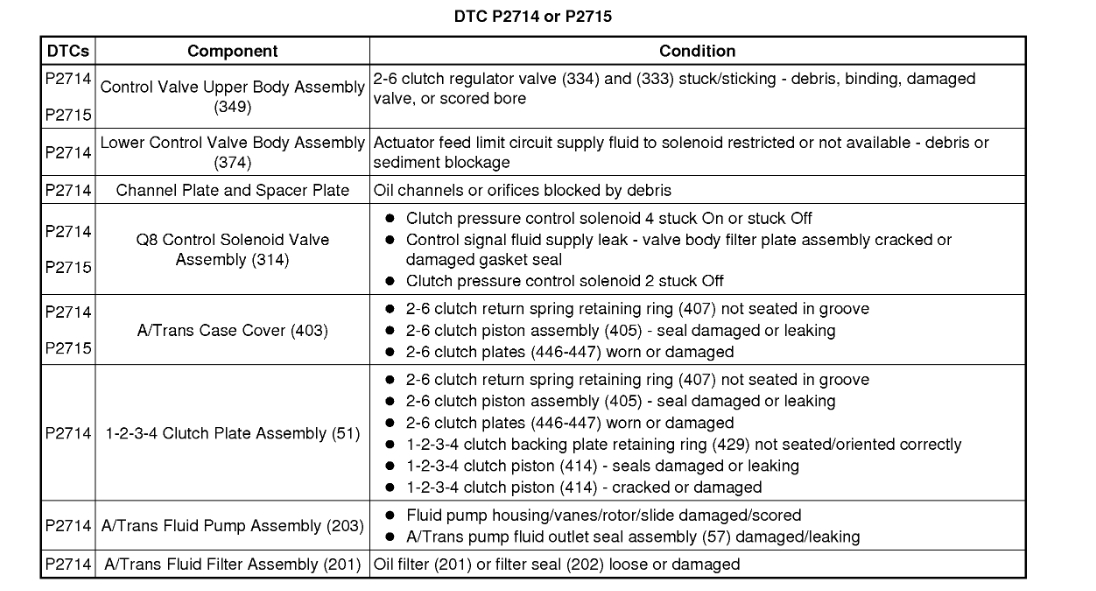
4. Listed in the table below, are conditions for each component that could set DTC P2714 or P2715. Carefully inspect each component for that condition. Repair or replace as necessary.
imageOpen In New TabZoom/Print
Repair Instructions
Note:
Perform the Reset Transmission Adapts See: Automatic Transmission/Transaxle > Programming and Relearning > Reset Transmission Adapts following all transmission related repairs.
Before replacing the TCM, perform the Control Solenoid Valve and Transmission Control Module Assembly Inspection See: Automatic Transmission/Transaxle > Component Tests and General Diagnostics > Control Solenoid Valve and Transmission Control Module Assembly Inspection.
Perform the Diagnostic Repair Verification See: A L L Diagnostic Trouble Codes ( DTC ) > Verification Tests > Diagnostic Repair Verification after completing the diagnostic procedure.
Control Valve Lower Body and Upper Body Replacement See: Valve Body, A/T > Removal and Replacement > Control Valve Lower Body and Upper Body Replacement
Low and Reverse Clutch and 1-2-3-4 Clutch Plate Removal See: Automatic Transmission/Transaxle > Overhaul > 8. Low and Reverse Clutch and 1-2-3-4 Clutch Plate Removal
Control Module References See: Vehicle > Programming and Relearning for control solenoid valve assembly replacement, setup, and programming
Check out the images (below). Let us know how it goes
Images (Click to enlarge)
Oct 6, 2019 at 8:58 AM