Good afternoon,
There is no easy way to get to the sensor. You need small hands and a lot of patience. The engineers must have had a bad day when they designed that one.
I attached the procedure and some pictures for you. I also attached a flow chart for the code to be sure it is the sensor. Codes rarely identify bad parts, just failed systems.
Roy
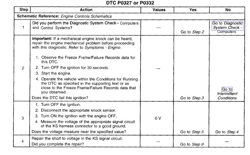
CIRCUIT DESCRIPTION
The Knock Sensors (KS) produce an IAC signal under all engine operating conditions. The Powertrain Control Module (PCM) calculates the average voltage range of each KS signal. If the KS system is operating normally, the PCM should monitor the KS voltage varying above and below a calculated average voltage. If the PCM detects a KS 1 signal voltage or a KS 2 voltage signal within the calculated average voltage range, a DTC will be set. A DTC P0327 refers to bank 1 knock sensor. A DTC P0332 refers to bank 2 knock sensor.
CONDITIONS FOR RUNNING THE DTC
DTCs P0101, P0102, P0103, P0117, P0118, P0121, P0122, P0123, P0125, P0336, P0341, P0502, P0503, P1114, P1115, or P1121 are not set.
The engine speed is between 1,000-2,000 RPM.
The throttle angle is more than 10 percent.
The engine load is more than 40 percent.
The Engine Coolant Temperature (ECT) is more than 60°C (140°F).
The maximum spark retard is less than 15 degrees.
The system voltage is more than 9 volts.
The engine run time is more than 30 seconds.
CONDITIONS FOR SETTING THE DTC
The PCM detects a knock sensor 1 or knock sensor 2 voltage within the calculated average voltage range.
ACTION TAKEN WHEN THE DTC SETS
The control module illuminates the Malfunction Indicator Lamp (MIL) on the second consecutive ignition cycle that the diagnostic runs and fails.
The control module records the operating conditions at the time the diagnostic fails. The first time the diagnostic fails, the control module stores this information in the Failure Records. If the diagnostic reports a failure on the second consecutive ignition cycle, the control module records the operating conditions at the time of the failure. The control module writes the operating conditions to the Freeze Frame and updates the Failure Records.
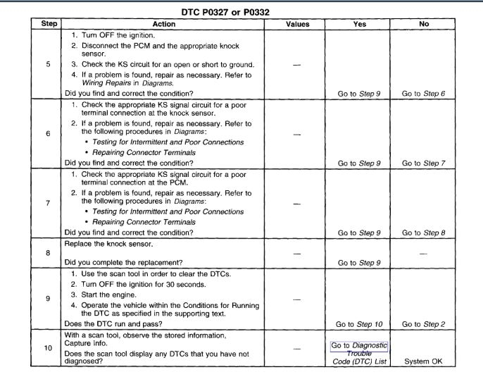
CONDITIONS FOR CLEARING THE MIL/DTC
The control module turns OFF the Malfunction Indicator Lamp (MIL) after 3 consecutive ignition cycles that the diagnostic runs and does not fail.
A current DTC, Last Test Failed, clears when the diagnostic runs and passes.
A history DTC clears after 40 consecutive warm-up cycles, if no failures are reported by this or any other emission related diagnostic.
Use a scan tool in order to clear the MIL and the DTC.
REMOVAL PROCEDURE
CAUTION: Refer to Knock Sensor Service Caution in Service Precautions.
imageOpen In New TabZoom/Print
1. Turn OFF the ignition.
2. Raise the vehicle. Refer to Lifting and Jacking the Vehicle.
3. Remove the bolts from the splash shield.
4. Drain the cooling system. Refer to Draining and Filling Cooling System in Cooling System.
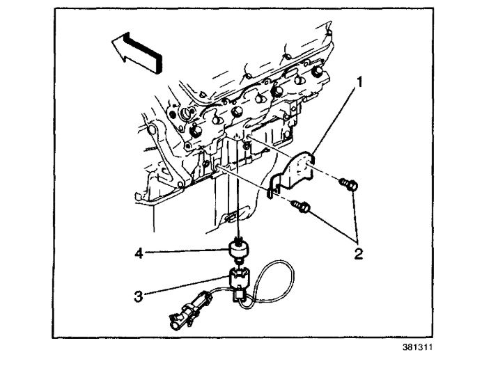
5. Remove the bolts (2) from the knock sensor heat shield (1) located under the freeze plug or block heater if equipped.
6. Disconnect the knock sensor wiring harness connector (3) from the knock sensor (4).
imageOpen In New TabZoom/Print
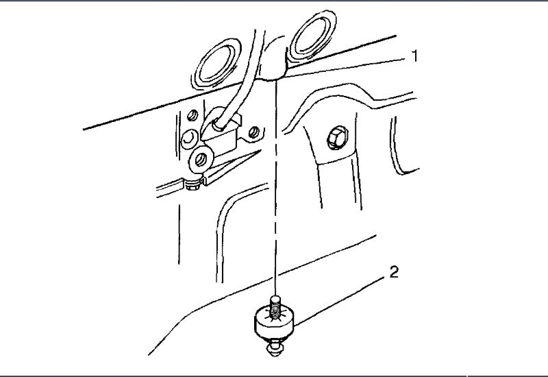
7. Remove the knock sensor (2) from the engine block (1).
INSTALLATION PROCEDURE
NOTE: Refer to Fastener Notice Fastener Notice in Service Precautions.
IMPORTANT: Do Not apply thread sealant to sensor threads. The sensor is coated at factory and applying additional sealant will affect the sensor's ability to detect detonation.
imageOpen In New TabZoom/Print
1. Install the knock sensor (2) into the engine block (1).
Tighten
Tighten the knock sensor to 19 N.m (14 lb ft).
2. Install the knock sensor heat shield
Tighten
Tighten the bolts to 60 N.m (44 lb ft).
3. Connect the knock sensor electrical connector to the knock sensor.
4. Install the splash shield.
5. Lower the vehicle.
6. Fill the cooling system. Refer to Draining and Filling Cooling System in Cooling System.
Images (Click to enlarge)
Jun 30, 2020 at 12:43 PM