Can I ask if the high beams work on both sides? If so, let's check for power at the wht/drkblu wire at the connector, also let's check the blk wire for ground this guide can help.
https://www.2carpros.com/articles/how-to-use-a-test-light-circuit-tester
If you don't have power and the ground is good chances are the BCM is going out, but did you look at the headlight bulb electrical connector? Sometimes they can burn and cause a bad connection. To confirm the BCM failure you will need to do a CAN scan. You can get a CAN scanner (Controller Area Network) which will work on most cars from Amazon.
Here is a video to show you how:
https://youtu.be/u-4syLc-ifQ
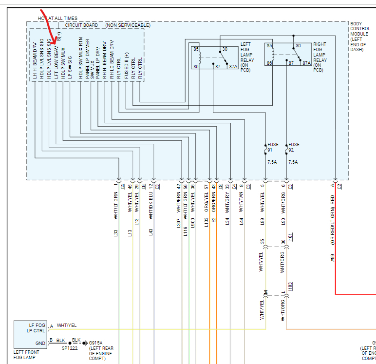
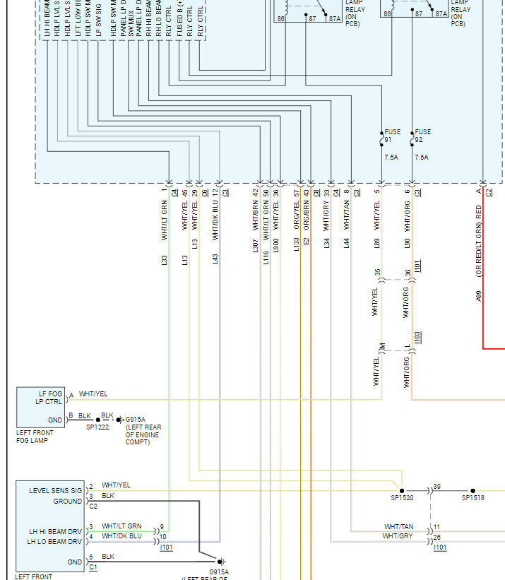
Or you can send the BCM to be tested and if found bad they can rebuild the unit for you. Here is the location of the BCM and how to change it out. Also, I have included the wiring diagrams for the left headlight so you can see how the system works.
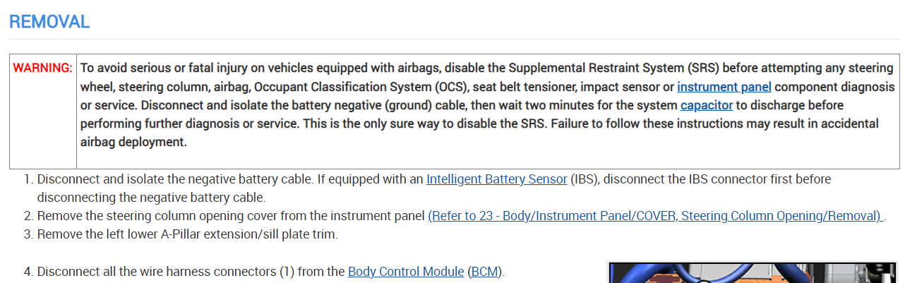
Disconnect and isolate the negative battery cable. If equipped with an Intelligent Battery Sensor (IBS), disconnect the IBS connector first before disconnecting the negative battery cable.
Remove the steering column opening cover from the instrument panel (Refer to 23 - Body/Instrument Panel/COVER, Steering Column Opening/Removal).
Remove the left lower A-Pillar extension/sill plate trim.
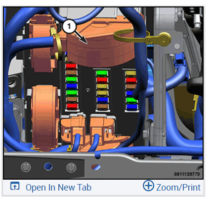
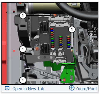
Disconnect all the wire harness connectors (1) from the Body Control Module (BCM).
Remove the fasteners (1) that secure the BCM brackets to the instrument panel carrier, outboard of the steering.
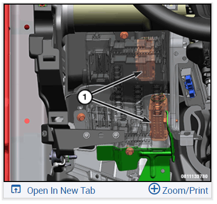
When removing the BCM, disconnect the wire harness connectors (1) from the back of the BCM.
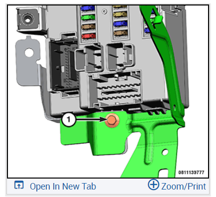
Remove the BCM to bracket mounting fastener (1).
If necessary, separate the BCM from the bracket.
If removed, install the BCM to the mounting bracket. Install the fastener (1) and tighten the screw to the proper (Torque Specifications) .
Position the BCM with mounting brackets to the instrument panel support structure outboard of the steering column as a unit and connect the wire harness connectors (1) to the back of the BCM.
Install the fasteners (1) that secure the BCM and BCM mounting bracket to the instrument panel support structure. Tighten the screws to the proper (Torque Specifications) .
Connect the wire harness connectors (1) to the BCM.
Install the left lower A-Pillar extension/sill plate trim.
Install the steering column opening cover to the instrument panel (Refer to 23 - Body/Instrument Panel/COVER, Steering Column Opening/Installation) .
Connect the negative battery cable. If equipped with an Intelligent Battery Sensor (IBS), connect the IBS connector to the negative battery cable.
Using the scan tool, perform the “IBS calibration” routine. If this is not completed, the Electronic STOP/START (ESS) function will not operate.
If this Electronic Control Unit (ECU) is being replaced with a new unit, programing of the BCM is required, (Refer to 08 - Electrical/8E - Electronic Control Modules/MODULE, Body Control/Module Programming) .
NOTE:
If this Electronic Control Unit (ECU) is being replaced with a new unit, a diagnostic scan tool MUST be used to determine if alignment of the PROXI configuration data into the new ECU is needed. If PROXI alignment is needed, follow the routine outlined in the diagnostic scan tool for PROXI Configuration Alignment under the Guided Diagnostics menu.
Check out the images (below). Please upload pictures or videos of the problem so we can see what's going on.
Images (Click to enlarge)
Dec 4, 2023 at 11:04 AM