In the classroom there are different ways of describing electrical theory, but for people like mechanics who are accustomed to being able to see and manipulate things in their hands, let my start this way.
Suppose you have a compressed air system in your shop that develops 100 psi. If you were to close the valve at the tank, what would you see for pressure at any point in the shop? 0 psi everywhere. The battery is like the tank. It's easy to see if the 12 volts is disconnected, you'd see 0 volts everywhere in the car. (Voltage is electrical pressure).
The other side of the circuit is harder to visualize. If the air valve at the tank is opened, and all of the outlets around the shop are turned off, you'd have 100 psi in all of the pipes. That's not normal operation though. Normal operation is to have air flowing through an air tool. This way, you will have 0 psi after the air leaves the tool. That means there was a drop of 100 psi between the tank and the tool. Almost all of that is across the tool, and a small percentage of it is caused by the restrictiveness of the pipes. All of this requires the air is able to reach atmospheric pressure, or for our purposes, 0 psi which is after the tool.
In the car, current has to flow from the power supply, (air tank), (5.0 volts in this case, developed inside the PCM), through the wires, (pipes), through the throttle position sensor, (air tool), through more wire, then to ground, (atmospheric pressure).
Suppose you were to block the exhaust port in the air tool. Now you'd see 100 psi all the way to that blockage, including inside the tool. The same thing happens when you block current flow after the TPS. You'll see 5.0 volts everywhere in the circuit, including the TPS, all the way up to that break. If you could imagine connecting a pressure gauge to the air tool, you'd measure 100 psi everywhere up to the blockage, and 0 psi after it. We find the break in the electrical circuit the same way, but with a voltmeter to measure electrical pressure. You'll find 5.0 volts where it is supposed to be at the 5.0-volt feed terminal on the sensor, but also on the ground terminal, and the ground wire, up to the break.
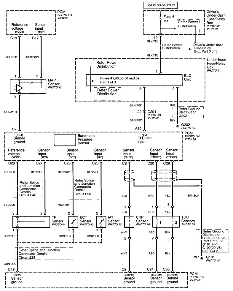
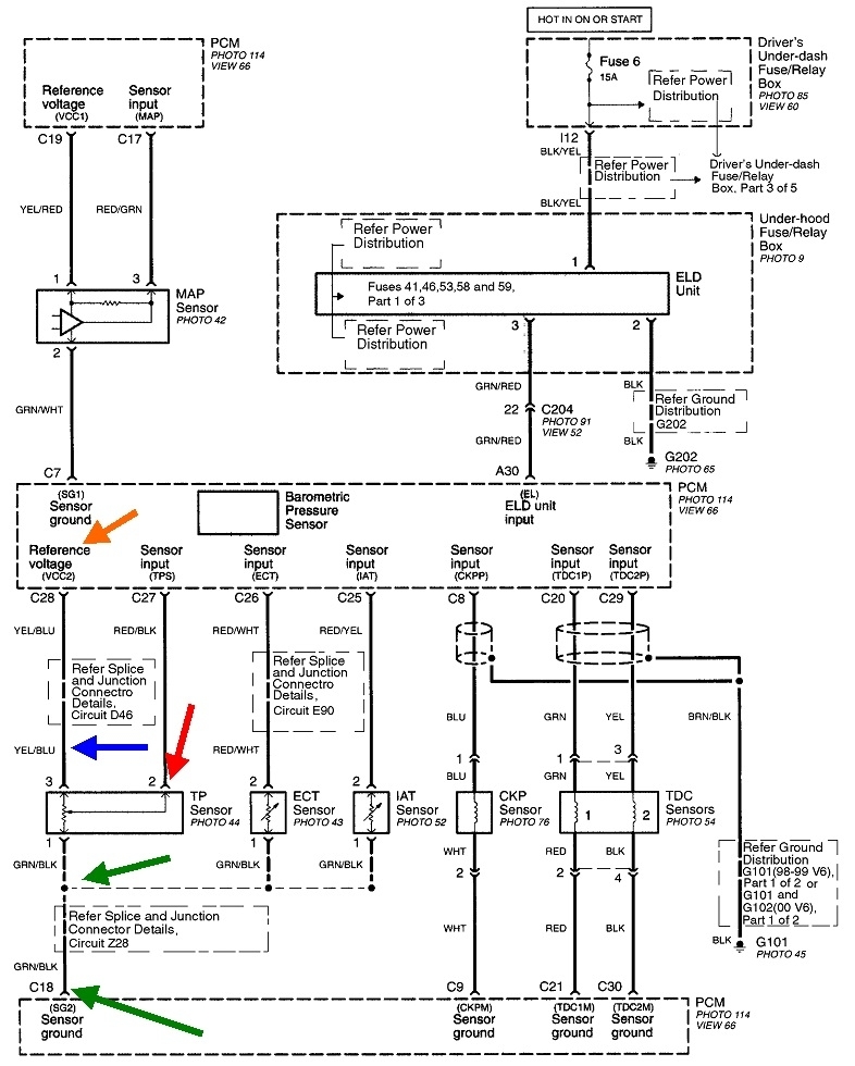
This break, or "open circuit", can be anywhere from the terminal inside the sensor, all the way back to a defect inside the PCM, but we can narrow it down by the fact it is affecting other sensors too. We have to look for what they all have in common. The first diagram is the part that shows some of the sensors in question. The second one is the same thing, but I added some nifty arrows to help explain this.
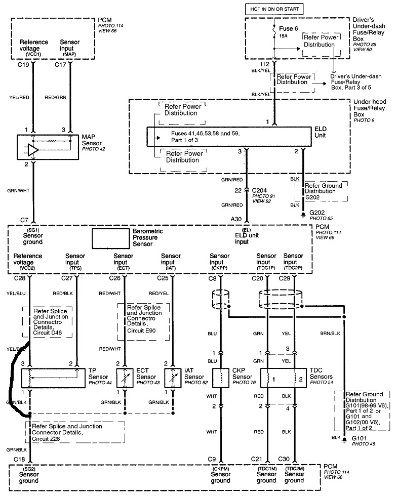
Your mechanic suggested there is a short to power. That is what is shown in the third diagram where I added the heavy black line. In fact, that can not put voltage on the green / black wire. It draws the 5.0-volt supply down to 0 volts, so if your mechanic was right about the short to power, you'd be seeing 0 volts for all the sensor readings, and your fault codes would all refer to "Intake Air Temperature Circuit Low Input", for example, not high.
I'm sorry if I'm making this more confusing than it needs to be. The concept is really very simple and straight-forward, but it can be hard to grasp at first.
There's three more important points of great value I should add. The first one has to do with throttle position sensors. You see where 5.0 volts is applied to the terminal with the yellow / blue wire, (blue arrow), and the terminal with the green / black wire is grounded and will have 0 volts. Inside the sensor is a carbon strip with one end connected to each of those terminals. The closer along that strip you get to the 5.0-volt terminal, the closer the voltage will also get to 5.0 volts. In the middle of the strip, it's halfway between 5.0 volts and 0 volts, so you'll see 2.5 volts. The signal terminal is a movable contact that slides along that carbon strip, and it sees the voltage at the point it's touching. That contact is tied to the throttle blade, so as the throttle is opened more and more, the voltage seen on the signal wire goes higher and higher. That voltage is what is seen on the red / black wire, (red arrow), that is the input to the PCM.
When the green / black ground circuit is open, (broken), as with the air flow blocked at the air tool, 5.0 volts is seen all through the TPS wiring and sensor, including on the signal terminal. At this point I have to add one more critical tidbit. The TPS has mechanical stops inside it that prevent the movable contact from going lower than 0.5 volts or higher than 4.5 volts. Those numbers are for training purposes. In actual practice, you could find the range from idle to wide-open-throttle might be 0.72 volts to 4.24 volts, for example. The actual values are irrelevant, but the important point is the signal voltage will never reach 0.0 volts or 5.0 volts, . . . unless there is a break in the circuit.
If the 5.0-volt feed wire is open, you'll have 0.0 volts everywhere in the TPS. If its ground circuit is open, you'll see 5.0 volts everywhere. Those two voltages can only occur when there's a defect in the circuit, and those are the values that trigger the diagnostic fault codes. This is why you see 5.0 volts on the ground wire at the TPS. You'll find that on the signal wire too.
For my next comment of great value, you'll notice all the ground wires for all the sensors do not actually go to ground. They go back to the PCM, then they go to ground on one of the computer's multiple ground wires. They do that so current flowing through the sensors can be monitored by circuitry inside the computer. As a result of some of the electrical pressure, (voltage) being dropped across that circuitry, you will actually read close to 0.2 volts on the sensors' ground wires. When the previous owner added his external ground wire, he got the sensors working properly, but he bypassed that monitoring circuit in the PCM. That would confuse the PCM, and while there might not be a fault code available for that defect, it could stop it from running some of the other hundreds of tests it runs continually while you're driving. That means it might not detect certain other defects or set fault codes for them, that is, until you repair the circuit. That's when those tests will resume, and any previously-undetected problems will be seen, and new fault codes will set.
If your eyeballs aren't spinning by now, this can all be boiled down to the green / black wire has to have a break in it between the two green arrows. That is the only section that includes the throttle position sensor, intake air temperature sensor, and the engine coolant temperature sensor.
To add some more confusion related to the two-wire IAT and ECT sensors, they too are fed with the carefully-regulated 5.0 volts from inside the PCM, but only the ground and signal wires go to the actual sensors. The 5.0-volt feed circuits include a resistor inside the PCM that drops some of that 5.0 volts. The rest shows up on the red / white and red / yellow signal wires. Temperature sensors have just one component inside them. That is a "thermistor" which is a resistor that changes value with changes in temperature. As temperature increases, the resistance goes down, so more current flows through the circuit, more of the 5.0 volts is dropped across the resistor inside the PCM, and less voltage is left to be dropped across the sensor. To say that a different way, as temperature goes up, the voltage on the signal wire goes down. As with the TPS, the acceptable range of signal voltage is 0.5 to 4.5 volts. It will never get down to 0 volts unless you ground the signal wire with a jumper wire. It will never get up to 5.0 volts unless you unplug the connector or there's a break in either wire.
For my last comment, I can't say specifically for other car brands, but I do know if you ground the 5.0-volt feed circuit to any sensor on a Chrysler product, nothing will be damaged. The computer will shut the supply down to protect it. To reset it, you have to turn the ignition switch off and back on after the short is removed.
Images (Click to enlarge)
Jan 4, 2020 at 12:39 PM