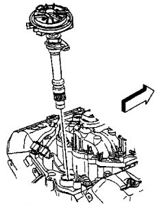
DISTRIBUTOR (HVI - HIGH VALUE IGNITION SYSTEM) The C/K model vehicles equipped with a 5.7L engine use the HVI system. The "distributor" is called the High Voltage Switch (HVS). System is also referred to as the HVI/HVS system. The HVS includes a camshaft position sensor. Removal 1. Turn OFF the ignition switch. 2. Remove the spark plug wires from the distributor cap. 3. Remove the electrical connector from the base of the distributor. 4. Remove the two screws that hold the distributor cap to the housing. 5. Discard the screws. 6. Remove the distributor cap from the housing. 7. Use a grease pencil in order to note the position of the rotor in relation to the distributor housing. The mark is identified in the illustration as the number "1". See Fig. 4 . 8. Mark the distributor housing and the intake manifold with a grease pencil. 9. Remove the mounting clamp hold down bolt. 10. Remove the distributor. See Fig. 5 . 11. As the distributor is being removed from the engine, watch the rotor move in a counter-clockwise direction about 42 degrees. this will appear as slightly more than one o'clock position. 12. Note the position of the rotor segment. Place a second mark on the base of the distributor. This will aid in achieving proper rotor alignment during the distributor installation. The second mark on the distributor housing is identified in the graphic as number 2. See Fig. 6 . Installation CAUTION: HVS ("distributor") is installed in a fixed, nonadjustable position. Base timing is computer controlled and cannot be adjusted by rotating HVS. Attempting to do so may result in crossfire and misfire conditions. If the malfunction indicator lamp turns on, and a DTC P1345 sets after installing the distributor, this indicates an incorrectly installed distributor. NOTE: There are two procedures available to install the distributor. Use installation procedure No. 1 when the crankshaft has NOT been rotated from the original position. Use installation procedure No. 2 when any of the following components are removed: � � � Intake Manifold � � � Cylinder Head � � � Camshaft � � � Timing Chain or Sprockets � � � Complete Engine Page 1 of 3 REMOVE/INSTALL/OVERHAUL - 5.7L -1998 GMC Pickup K1500 1/24/2009 src="https://www.2carpros.com/forum/automotive_pictures/62217_p1345a_1.jpg" alt="https://www.2carpros.com/forum/automotive_pictures/62217_p1345a_1.jpg" />
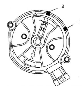
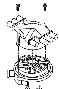
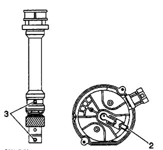
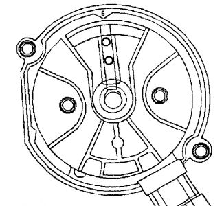
1. If Installing a new distributor assembly, place two marks on the new distributor housing in the same location as the two marks on the original housing. 2. Remove the new distributor cap, if necessary. 3. Align the rotor with mark made at location 2. See Fig. 6 . 4. Guide the distributor into the engine. Make sure that the mounting hole in the distributor hold- down base is aligned over the mounting hole in the intake manifold. 5. As the distributor is being installed, observe the rotor moving in a clockwise direction about 42 degrees. 6. Once the distributor is completely seated, the rotor segment should be aligned with the mark on the distributor base in the location number "1". See Fig. 4 . If the rotor segment is not aligned with the number "1" mark, the driven gear teeth and the camshaft have meshed one or more teeth out of alignment. In order to correct this condition, remove the distributor and reinstall it. 7. Install the distributor mounting clamp. Tighten the distributor clamp bolt to 18 ft. lbs. (25 N.m). Install the distributor cap. 8. Install two NEW distributor cap screws. Tighten the screws to 21 INCH lbs. (2.4 N.m). See Fig. 7 . 9. Install the electrical connector to the distributor. 10. Install the spark plug wires to the distributor cap. Procedure 2 1. Position No. 1 cylinder to Top Dead Center (TDC) of the compression stroke. 2. Align white paint mark on the bottom stem of the distributor, and the pre-drilled indent hole in the bottom of the gear (3 in illustration). See Fig. 8 . 3. With the gear in this position, the rotor segment should be positioned as shown (2 in illustration). See Fig. 8 . The alignment will not be exact. If the driven gear is installed incorrectly, the dimple will be approximately 180 degrees opposite the rotor segment when it is installed in the distributor. CAUTION: If the malfunction indicator lamp is turned on after installing the distributor, and a DTC P1345 is found, the distributor has been installed incorrectly. Refer to installation Procedure 2 for proper distributor installation. NOTE: The OBD II ignition system distributor driven gear and rotor can be installed in multiple positions. In order to avoid mistakes, make sure to mark the distributor in the following positions: � � � The distributor driven gear. � � � The distributor shaft. � � � The rotor holes for the same mounting position upon reassembly. Installing the driven gear 180 degrees out of alignment, or locating the rotor in the wrong holes, will cause a no-start condition. 4. Using a long screw driver, align the oil pump drive shaft to the drive tab of the distributor. 5. Guide the distributor into the engine. Ensure the spark plug towers are perpendicular to the centerline of the engine. 6. Once the distributor is properly seated, the rotor segment should be aligned with the pointer cast into the distributor base. The pointer must have an "8" cast onto it (a "6" indicates a V6 engine component).See Fig. 9 . If the segment does not come within a few degrees of the pointer, the gear mesh between the distributor and the camshaft may be off a tooth or more. If this is the case, repeat the procedure again in order to achieve proper alignment. 7. Install the distributor mounting clamp. Tighten the distributor clamp bolt to 18 ft. lbs. (25 N.m). Install the distributor cap. 8. Install the New distributor cap screws. Tighten the screws to 21 INCH lbs. (2.4 N.m). See Fig. 7 . 9. Install the electrical connector to the distributor. Install the spark plug wires to the distributor. Premature engine wear or damage may result. CAUTION: If the malfunction indicator lamp is turned on after installing the distributor, and a DTC P1345 is found, the distributor has been installed incorrectly. Refer to installation Procedure 2 for proper distributor installation. Page 3 of 3 REMOVE/INSTALL/OVERHAUL - 5.7L -1998 GMC Pickup K1500 1/24/2009
Saturday, January 24th, 2009 AT 8:29 AM