Circuit Description
The 2-3 shift solenoid valve is used to control fluid flow acting on 2-3 shift valves. Solenoid is a normally-open exhaust valve used in conjunction with 1-2 shift solenoid valve to allow 4 different shifting combinations. See SHIFT SOLENOID COMBINATIONS table. Solenoid is attached to control valve body. Ignition voltage is supplied directly to solenoid through fused circuit. Control module commands solenoid on or off through ground circuit. DTC P0758 is set if control module detects a continuous open, short to ground or short to voltage in 2-3 shift solenoid circuit.
Conditions For Running DTC P0758
DTC will run under the following conditions:
System voltage is 8-19 volts.
Engine speed is greater than 450 RPM for 5 seconds.
Engine is not in fuel cutoff mode.
Conditions For Setting DTC P0758
DTC will set if one of the following conditions is met for 5 seconds:
Control module commands solenoid on and voltage remains high (battery voltage).
Control module commands solenoid off and voltage remains low (zero volts).
Action Taken By Control Module
Control module performs the following actions if DTC is set:
Illuminates MIL at first failure signal.
Commands 3rd gear only.
Control module commands maximum line pressure.
Inhibits TCC engagement.
Freezes shift adapts from being updated.
Records operating conditions when conditions for running DTC are met.
DTC P0758 is recorded in history.
Diagnostic Procedure
Perform OBD system check. See ON-BOARD DIAGNOSTIC (OBD) SYSTEM CHECK under DIAGNOSIS & TESTING. After performing OBD system check, go to next step.
Connect scan tool to DLC. Turn ignition on, engine off. Using scan tool, record freeze frame and failure records for reference, and then clear DTCs. If DTCs P0740, P0758, P0785 or P1860 is present, go to next step. If DTCs P0740, P0758, P0785 and P1860 are not present, go to step 4 .
Check condition of shift solenoid circuit fuse. See WIRING DIAGRAMS . If fuse is open, go to step 12 . If fuse is okay, go to step 5 .
Using scan tool, command 2-3 shift solenoid valve on and off while listening to bottom of transmission oil pan. If solenoid clicks as commanded, see DIAGNOSTIC AIDS . If solenoid does not click, go to next step.
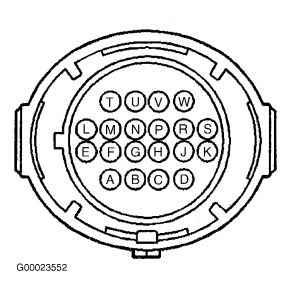
Turn ignition off. Disconnect transmission 20-pin in-line harness connector. Connect appropriate jumper harness to engine side of in-line harness connector. Turn ignition on, engine off. Using test light connected to ground, probe terminal "E" of jumper harness. See CONNECTOR IDENTIFICATION under DIAGNOSIS & TESTING. If test light illuminates, go to next step. If test light does not illuminate, go to step 15 .
Connect test light between terminals "B" and "E" of jumper harness. Using scan tool, command 2-3 shift solenoid valve on and off 3 times. If test light illuminates with scan tool command, go to step 8 . If test light does not illuminate with scan tool command, go to next step.
If test light is always on, go to step 16 . If test light is not always on, go to step 17 .
Connect appropriate jumper harness to transmission side of in-line harness connector. Measure resistance between terminals "B" and "E" of jumper harness. See CONNECTOR IDENTIFICATION under DIAGNOSIS & TESTING. If resistance is 19-31 ohms, go to next step. If resistance is not 19-31 ohms, leave DVOM connected and go to step 10 .
Measure resistance between ground and terminal "B" of jumper harness, and then between ground and terminal "E" of jumper harness. If both measurements are greater than 250 k/ohms, see DIAGNOSTIC AIDS . If both measurements are not greater than 250 k/ohms, go to step 11 .
Remove transmission oil pan. Disconnect transmission wiring harness assembly from 2-3 shift solenoid valve. If resistance is 19-31 ohms, go to step 18 . If resistance is not 19-31 ohms, go to step 19 .
Remove transmission oil pan. Disconnect transmission wiring harness assembly from 2-3 shift solenoid valve. Measure resistance between ground and terminals of 2-3 shift valve. If both measurements are greater than 250 k/ohms, go to step 18 . If both measurements are not greater than 250 k/ohms, go to step 19 .
NOTE:Condition affecting shift solenoid valve circuit may be caused by a fault in other circuits spliced to shift solenoid valve circuit.
Check 2-3 shift solenoid valve ignition feed circuit for short to ground between engine wiring harness junction block and transmission 20-pin in-line harness connector. Repair as necessary. After repairs, go to step 21 . If circuit is okay, go to next step.
NOTE:Condition affecting shift solenoid valve circuit may be caused by a fault in other circuits spliced to shift solenoid valve circuit.
Check 2-3 shift solenoid valve ignition feed circuit for short to ground between 2-3 shift solenoid valve and transmission 20-pin in-line harness connector. If circuit is shorted, go to step 18 . If circuit is okay, go to next step.
Check each solenoid for short to ground. Repair as necessary. After repairs, go to step 21 .
NOTE:Condition affecting shift solenoid valve circuit may be caused by a fault in other circuits spliced to shift solenoid valve circuit.
Check for open in 2-3 shift solenoid valve ignition feed circuit. Repair as necessary. After repairs, go to step 21 .
Check 2-3 shift solenoid valve control circuit for short to ground between transmission 20-pin in-line harness connector and control module. Repair as necessary. After repairs, go to step 21 . If circuit is okay, go to step 20 .
Check 2-3 shift solenoid valve control circuit for open or short to voltage between transmission 20-pin in-line harness connector and control module. Repair as necessary. After repairs, go to step 21 . If circuit is okay, go to step 20 .
Replace transmission wiring harness assembly. After repairs, go to step 21 .
Replace 2-3 shift solenoid valve. After repairs, go to step 21 .
Replace control module. After replacement, program control module. See COMPUTER RELEARN PROCEDURES article in GENERAL INFORMATION. After repairs, go to next step.
Using scan tool, clear DTCs. Test drive vehicle in "D4" range. Ensure when control module commands 2-3 shift solenoid on, feedback voltage decreases to zero, and then increases to battery voltage when commanded off. Ensure each condition is met for at least 5 seconds. Check for DTCs. If DTC P0758 does not return, system is okay. If DTC P0758 returns, repeat step 1 .
Shop: Mitchell 1 Admin
Date: 6/11/2007 2:58:06 PM
TIP
Malfunction indicator lamp (MIL) on, trans stuck in 2nd or 3rd gear, instrument cluster inoperative (diagnose & replace ignition switch if necc). See bulletin #01-07-30-002. Techs in field report IGN switch failure is common & may cause multiple symptoms with trans, IPC or other IGN feed circuits. (DTCs) P0740, P0753, P0758, P0785, P1860 may be set.
Most likely cause of this condition may be a loss of power to the transmission on circuit 1020.
To verify, with the ignition switch in the run position, test for battery voltage at the appropriate fuse listed below.
1997 s/t trans 24
1998-2003 s/t (old style) cluster 11
2002-2003 s/t (new style) ignition 0
1997-2000 c/k (old style) trans 20
1999-2003 c/k (new style) ignition 0
1997-2002 g-van trans 20
2003 g, h-van ignition 0
2003 H2 ignition 0
After IGN switch replacement, VTD (theft deterrent) relearn must be performed
Wednesday, March 4th, 2009 AT 8:43 PM