Good morning,
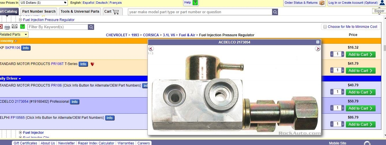
The regulator is on the fuel rail. I attached a picture for you to view. I also attached the part for you as well.
It is between the fuel rails with a vacuum line attached.
Roy
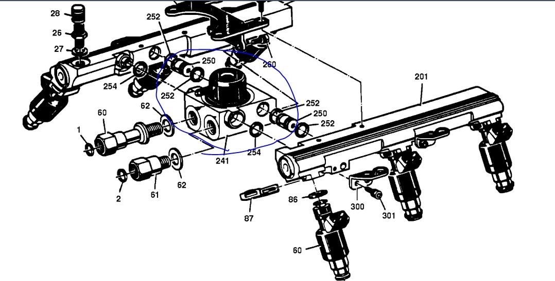
FUEL RAIL ASSEMBLY
An eight digit identification number is stamped on the left hand fuel rail (fueling even cylinders 2, 4, 6), as shown. Refer to this number if servicing or part replacement is required. Part names appear in the numbered list on the disassembled view.
NOTE: Use care in removing the fuel rail assembly, to prevent damage to the injector electrical connector terminals and the injector spray tips. Prevent dirt and other contaminants from entering open lines and passages. Fittings should be capped, and holes plugged, during servicing.
CLEAN: Before removal, the fuel rail assembly may be cleaned with a spray type engine cleaner, GM X-30A or equivalent, following package instructions. DO NOT soak fuel rails in liquid cleaning solvent.
REMOVE OR DISCONNECT:
1. Negative battery terminal.
2. Relieve fuel system pressure.
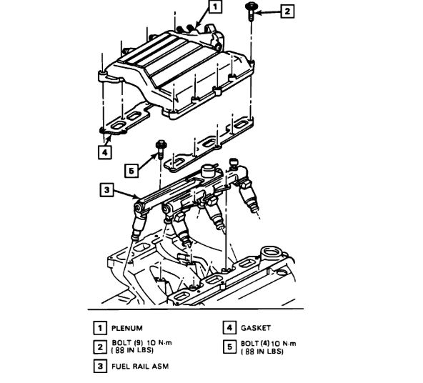
3. Intake manifold plenum.
4. Fuel line bracket bolt.
5. Fuel lines at rail. Use a back-up wrench on the fuel rail fittings to prevent them from turning.
6. Fuel inlet and return line O-rings (1, 2), and discard.
7. Vacuum line at pressure regulator.
8. Rail retaining bolts.
9. Injector electrical connectors.
10. Fuel rail assembly.
DISASSEMBLE:
Injector O-ring seal from spray tip end of each injector. Discard seals.
ASSEMBLE:
Lubricate new injector O-ring seals with clean engine oil, and install on spray tip end of each injector.
INSTALL OR CONNECT:
1. Fuel rail assembly in intake manifold. Tilt rail assembly to install injectors.
2. Fuel rail attaching bolts. Tighten fuel rail attaching bolts to 10 N-m (88 lb. in.).
3. Injector electrical connectors.
4. Vacuum line to pressure regulator.
5. New O-rings (1, 2) on fuel lines.
6. Fuel feed and return lines. Tighten fuel line nuts to 23 N-m (17 lb. ft.). Use a back-up wrench on the fuel rail fittings to prevent them from turning.
7. Negative battery terminal.
8. Fuel filler cap.
9. Turn ignition switch to the "ON" position for two seconds, then turn to the "OFF" position for ten seconds. Again turn to the "ON" position, and check for fuel leaks.
10. Intake manifold plenum.
11. Perform the "Idle Learn Procedure." The ECM will need to relearn the IAC valve pintle position following battery reconnect.
REMOVAL:
1. Disconnect the negative battery cable.
2. Relieve the fuel system pressure, see FUEL SYSTEM PRESSURE RELIEF.
3. Remove the intake manifold plenum, see INTAKE MANIFOLD PLENUM.
4. Remove the fuel line bracket bolt.
5. Remove the fuel lines at the fuel rail. Use a back-up wrench on the fuel fittings to prevent them from turning.
6. Remove the fuel inlet and return line O-rings and discard.
7. Disconnect the vacuum line at the pressure regulator.
8. Remove the fuel rail retaining bolts.
CAUTION: Use care in removing the fuel rail assembly, to prevent damage to the injector spray tips, and the injector electrical connector terminals. When removed, support the rail to prevent damage to its components. The fuel injector is serviced as a complete assembly only. Since it is an electrical component, it should not be immersed in any liquid cleaner.
9. Remove the injector O-ring from the tip of each injector, and discard.
INSTALLATION:
1. Lubricate the O-ring seals with clean engine oil, and install one on the tip of each injector.
2. Install the fuel rail assembly in the intake manifold. Tilt the fuel rail assembly in the intake manifold. Tilt rail to install the injectors.
3. Install the fuel rail mounting bolts, and tighten to 10 N-m (88 lb. in.).
4. Connect the fuel injector electrical connectors.
5. Put new O-rings on the fuel lines.
6. Attach the fuel feed and return line and tighten to 23 N-m (17 lb. ft.). Use a back-up wrench on the fuel fittings to prevent them from turning.
7. Check for fuel leaks:
a. Temporarily connect the negative battery cable.
b. With the engine "OFF" and the ignition "ON," check for fuel leaks.
c. Disconnect the negative battery cable.
8. Install the intake manifold plenum.
9. Connect the negative battery cable.
IDLE LEARN PROCEDURE: Any time the battery is disconnected, the programmed position of the IAC valve pintle is lost, and replaced with a default value. To return the IAC valve pintle to the correct position, perform the following procedure:
1. After restoring battery power, connect the Tech 1 "SCAN" tool.
2. Select "IAC SYSTEM," then select "IDLE LEARN" in the "MISC TEST" mode.
3. Proceed with idle learn as directed.
This procedure allows the ECM memory to be updated with the correct IAC valve pintle position, for the vehicle, and provide a stable idle speed.
Images (Click to enlarge)
Apr 5, 2020 at 10:02 AM