Fuel gauge not working properly

Tiny
L TIATOM
  • MEMBER
  • 2011 HYUNDAI I20
  • 1.2L
  • 4 CYL
  • 4WD
  • MANUAL
  • 65,000 MILES
Tank is fully filled.

Recently, my vehicle's fuel gauge is sometimes gets stuck at half mark but never to zero mark.

Reinsert the key as well as resetting by removing the battery doesn't work.
The gauge sometimes shows full, sometimes halfway.

Even when the key is removed, sometimes it stuck at halfway or full mark. This is very surprising!

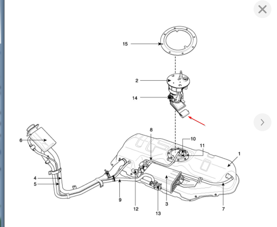
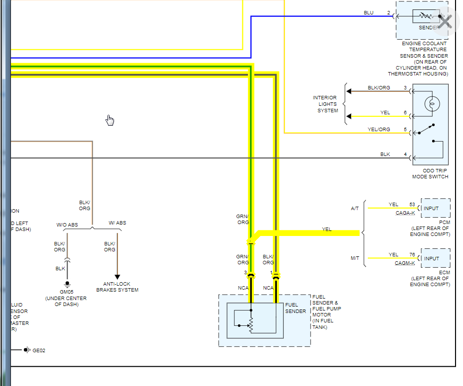
There is about 1 v at the wire of the fuel sending unit which shows voltage is okay. For 12 v, it will be fuel empty. On voltage reading, fuel system is okay.

Why this issue happen intermittently especially when key removed?
Saturday, November 21st, 2020 AT 3:23 AM

2 Replies

Tiny
KASEKENNY
  • MECHANIC
  • 18,907 POSTS
Just so I understand, when it gets stuck half way, even when you shut it off, it does not drop to the left? You have an analog (needle) gauge and not a digital gauge correct? Can you get a picture of this? We don't have your vehicle here in the USA so I don't have specific details on your vehicle but this is normally caused but the needle itself just getting stuck in that position.

I attached the wiring diagram from the USA version of your vehicle and it shows basically the same thing you are seeing. The level sensor is a float in the tank and when full, the voltage is low, when empty it gets closer to 12 volts. This is a direct feed to the ECM and cluster where the cluster just displays this voltage on the gauge.

Next tie it happens, try getting a picture of it and then try tapping gently on the cluster and see if the gauge will move. Clearly this would confirm that it is just the needle sticking.
Was this
answer
helpful?
Yes
No
Saturday, November 21st, 2020 AT 6:30 AM
Tiny
L TIATOM
  • MEMBER
  • 61 POSTS
  • 2011 HYUNDAI I20
  • 1.2L
  • 4 CYL
  • 4WD
  • 65,000 MILES
Here's a correct instrument cluster showing all the complete warning lights circuit for i20. No doubts.

Curious to know the physical internal structure of the PCB board, I dissembled the cluster and it's PCB layout is also attached herewith.

Now, on further investigation of the warning light indicators circuit say hand brake parking light, to my surprise, the diagram actually doesn't corresponds to the actual physical connection on PCB layout.

In case of hand brake light, this light is on whenever the switch is closed. And, same is the case for the oil pressure switch.

In the PCB layout, the corresponding brake led bulb comes across many extra components like a small SMD transistor. Same conditions for other led lights too. Whereas, in the actual diagram, no such transistors were shown. The LEDs brake and oil light lights on encircled on image when it's is grounded directly through switch.

Why is there transistor in this 2 particular case, and why not transistors are shown in the diagram It's really misleading.
Was this
answer
helpful?
Yes
No
Thursday, December 31st, 2020 AT 3:14 PM (Merged)

Please login or register to post a reply.

Sponsored links