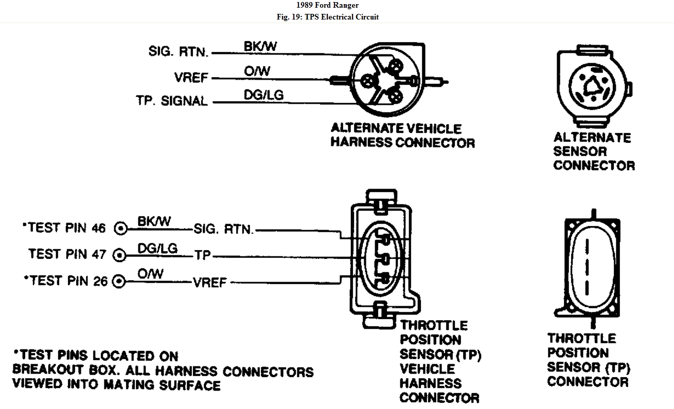
This is the by the book method, I will send the wiring diagram if you post your email, this will help with wire ID instead of using a breakout box, which I assume you don't have!
To prevent replacement of good components, be aware that the following non-EEC related areas may
be at fault: fuel lines, fuel filters, throttle body, fuel pump or contaminated fuel.
1. No Fuel Pressure: Electrical Check. Install fuel pressure gauge. Cycle key from off to on
several times to check if fuel pump runs. DO NOT crank engine. Pump should operate briefly
each time key is on. If pump runs as indicated, service or replace fuel pump as necessary. If
pump does not run as indicated, go to next step.
2. Checking For VPWR to ECA. Turn key off and wait 10 seconds. Disconnect ECA 60-pin
connector. Inspect connector for damaged pins, corrosion, or loose wires. Install breakout box
and connect ECA to it. With KOEO, DVOM on 20-volt scale, measure voltage between test
pins No. 37 and 40 at breakout box, and between test pins No. 57 and 60 at breakout box. If
either reading is less than 10.5 volts, go to TEST A2 - VEHICLE BATTERY, step 1). If
both readings are 10.5 volts or more, go to step 5).
3. Checking Continuity Between Fuel Pump Relay and Fuse On 2.3L Turbo Models. Does not
apply to trucks.
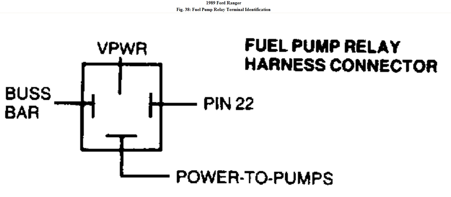
Fig. 38: Fuel Pump Relay Terminal Identification
4. Check Voltage To Power-To-Pumps Circuit On 2.3L Turbo Models. Does not apply to trucks.
5. Check Voltage to Power-to-Pump Circuit. With KOEO, breakout box installed and ECA
connected to it. Disconnect fuel pump circuit fuse (fuse No. 20). Reconnect fuel pump relay.
Set DVOM on 20 volt scale. Measure voltage between chassis ground and power-to-pump
circuit at fuel pump relay while cranking engine. If reading is less than 8 volts, go to next step.
If reading is 8 volts or more, check the following: open in power-to-pump circuit, open in fuel
pump and open in fuel pump ground circuit.
6. Checking BATT+ Circuit to Fuel Pump Relay. Turn key on, leaving engine off. Leave
breakout box installed and ECA connected, locate fuel pump relay. Set DVOM on 20-volt
scale. Measure voltage between chassis ground and BATT+ circuit at fuel pump relay. If
reading is less than 10.5 volts, repair open in BATT+ circuit between fuel pump relay and
battery positive post. Repeat QUICK TEST. If reading is 10.5 volts or greater, go to step 11).
7. Service Code 87: Checking VPWR Circuit to Fuel Pump Relay. Code 87 indicates a fuel pump
primary circuit failure. Possible causes are: inertia switch not reset or electrically open, faulty
fuel pump relay, ECA or open or shorted circuit. Turn key on, leaving engine off. Leave
breakout box installed and ECA connected. Locate fuel pump relay. Set DVOM on 20-volt
scale. Measure voltage between chassis ground and VPWR circuit at fuel pump relay. If
reading is 10.5 volts or more, go to next step. If reading is less than 10.5 volts, ensure inertia
switch is on. If inertia switch will not reset, replace switch. If switch is okay, repair open in
VPWR circuit between EEC power relay and fuel pump relay. Repeat QUICK TEST.
8. Checking Fuel Pump Circuit Continuity. Turn key off and wait 10 seconds. Leave breakout
box installed and ECA connected. With DVOM on 200-ohm scale, measure resistance between
fuel pump circuit at pump relay and test pin No. 22 at breakout box. If reading is 5 ohms or
more, repair open in fuel pump circuit. Repeat QUICK TEST. If reading is less than 5 ohms,
go to next step.
9. Checking For Short to Power. Disconnect ECA and fuel pump relay. With key on, breakout
box installed, set DVOM on 20-volt scale. Measure voltage between test pin No. 22 and
battery negative terminal. If voltage is less than one volt, go to next step. If voltage is more
than one volt, repair short circuit. Reconnect ECA and attempt to start vehicle. If vehicle fails
to start, replace ECA. Rerun QUICK TEST.
10. Checking For Short to Ground. Turn key off. Leave breakout box installed and disconnect
ECA. Disconnect fuel pump relay. With DVOM on 200K-ohm scale, measure resistance
between test pin No. 22 and test pins No. 40 and 60 at breakout box. If reading is less than 10K
ohms, repair short in fuel pump circuit. Repeat QUICK TEST. If reading is 10K ohms or more,
go to next step.
11. Checking Voltage at Power-to-Pump Circuit. Leave breakout box installed and ECA
disconnected. Install a jumper wire between test pin No. 22 and test pins No. 40 or 60 at
breakout box. Set DVOM on 20 volt scale. With KOEO, measure voltage between chassis
ground and power-to-pump circuit at fuel pump relay. If reading is 10.5 volts or more, replace
ECA and repeat QUICK TEST. If reading is less than 10.5 volts, replace fuel pump relay.
Connect ECA and repeat QUICK TEST.
12. Service Code 95: Check Inertia Switch. A KOEO code 95 indicates that one of the following
has occurred:
? Inertia switch not reset or electrically open.
? Open circuit in or between ECA and fuel pump.
? Faulty ground connection at fuel pump.
? Fuel pump secondary circuit shorted to power.
? Fuel pump relay contacts always closed.
? Faulty ECA.
Turn key off and wait 10 seconds. Locate and disconnect inertia switch. Set DVOM on 200-
ohm scale. Measure resistance of inertia switch. If resistance is less than 5 ohms, reconnect
inertia switch and go to next step. If resistance is more than 5 ohms, replace or reset inertia
switch and rerun QUICK TEST.
13. Verifying Fuel Pump is Off. With key off, listen for fuel pump noise. If fuel pump is off, go to
step 15). If fuel pump is on, go to next step.
14. Fuel Pump Relay Check. Turn key off. Remove fuel pump relay. If fuel pump turns off,
replace fuel pump relay. Repeat QUICK TEST. If fuel pump does not turn off, repair short to
power-to-pump circuit. Repeat QUICK TEST.
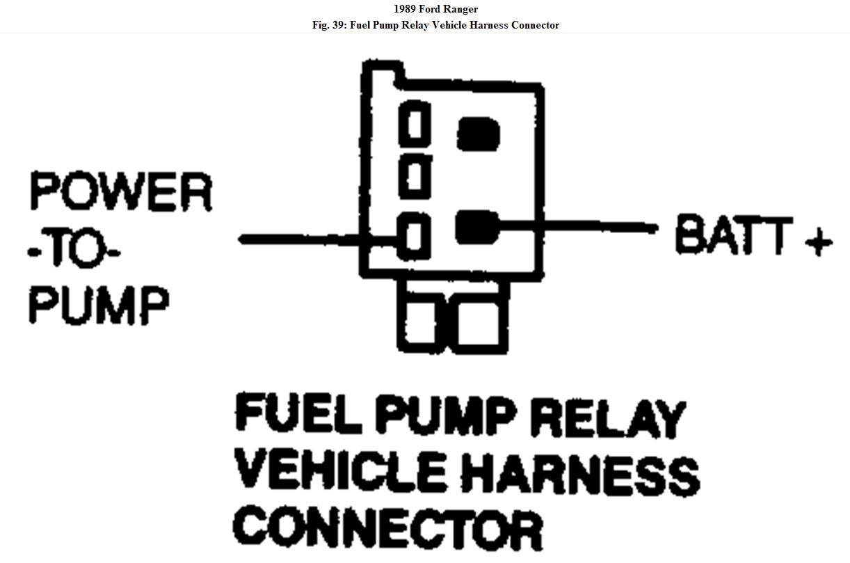
15. Checking Continuity of Fuel Pump Monitor (FPM) Circuit. Turn key off and wait 10 seconds.
Disconnect ECA 60-pin connector. Inspect connector for damaged pins, corrosion, or loose
wires. Install breakout box and leave ECA disconnected. Disconnect fuel pump relay. Set
DVOM on 200-ohm scale and measure resistance between test pin No. 8 at the breakout box
and power-to-pump circuit at the fuel pump relay harness. See Fig. 39. If resistance is less
than 5 ohms, go to next step. If resistance is greater than 5 ohms, repair open circuit and rerun
QUICK TEST.
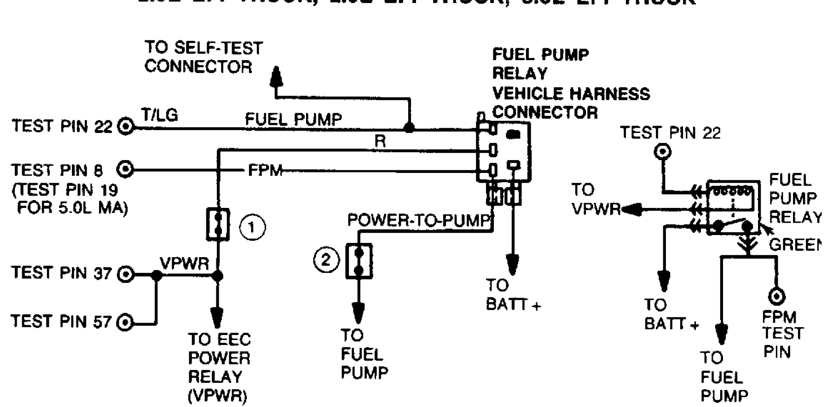
Fig. 39: Fuel Pump Relay Vehicle Harness Connector
16. Checking Continuity Between FPM Circuit and Ground. Turn key off. Install breakout box and
disconnect ECA. Disconnect fuel pump relay. Set DVOM on 200-ohm scale and measure
resistance between test pin No. 8 at the breakout box and battery negative terminal. If
resistance is less than 10 ohms, remove test set-up, reconnect fuel pump relay, replace ECA
and rerun QUICK TEST. If resistance is more than 10 ohms, remove test set-up and check the
following: open circuit in fuel pump, poor ground connection at fuel pump, or an open in
power-to-pump circuit.
17. Checking Fuel Pump Primary Circuit For Short to Ground. Turn key off and wait 10 seconds.
Install breakout box and disconnect ECA. Disconnect fuel pump relay and set DVOM on
200K-ohm scale. Measure resistance between test pins No. 22 and 40 at the breakout box. If
resistance is greater than 10K ohms, remove test set-up. Replace ECA, and rerun QUICK
TEST. If resistance is less than 10K ohms, remove test set-up. Repair short circuit and rerun
QUICK TEST.
18. Service Code 96: Checking BATT+ to Fuel Pump Relay. Service code 96 indicates a fuel
pump secondary circuit failure between the BATT+ supply and the FPM connection to the
POWER-to-PUMP connection. Possible causes are: faulty fuel pump relay or ECA, open
circuit. Turn key off and wait 10 seconds. Locate fuel pump relay. With the DVOM on 20-volt
scale, measure voltage between BATT+ circuit at fuel pump relay and battery negative. If
voltage is greater than 10.5 volts, go to next step. If voltage is less than 10.5 volts, repair open
circuit and rerun QUICK TEST.
19. Verifying Fuel Pump Operation. With key off, set DVOM on 20-volt scale. Connect DVOM
between POWER-to-PUMP circuit at fuel pump relay and battery negative post. Check voltage
while turning key to RUN position (one second) and OFF position (10 seconds). Repeat cycle
at least 5 times. If voltage is greater than 10.5 volts for approximately one second after key is
turned to RUN position, replace ECA and rerun QUICK TEST. If voltage is not to
specification, inspect relay harness connector and if okay, replace fuel pump relay.
20. Checking Continuity of Power-to-Pump Circuit. Turn key off and disconnect ECA 60-pin
connector. Inspect connector for damaged pins, corrosion, or loose wires. Install breakout box
and leave ECA disconnected. With DVOM on 200-ohm scale, measure resistance between test
pin No. 8 at breakout box and POWER-to-PUMP circuit at relay harness connector. If
resistance is less than 5 ohms, remove test set up, replace ECA, and rerun QUICK TEST. If
resistance is more than 5 ohms, repair open circuit between FPM connecting splice and relay.
Rerun QUICK TEST.
21. Continuous Memory Code 95: Checking EEC-IV Harness. A continuous code 95 indicates that
one of the following conditions has occurred intermittently: Open circuit in or between the fuel
pump and FPM circuit at the ECA. Faulty ground circuit at the fuel pump. Start engine and
perform WIGGLE TEST on harness assembly to fuel pump, and to pump ground circuit
harness. Lightly tap inertia switch and pump to simulate road shock. Check for engine miss or
stumble while performing test. With key off, check harness connectors for corrosion or
damage. Isolate and repair any faults that are found, clear Code 95 and rerun QUICK TEST. If
no fault is found, go to next step.
22. Checking FPM Circuit. Turn key off. Disconnect ECA 60-pin connector. Inspect connector for
damaged pins, corrosion, or loose wires. Install breakout box and leave ECA disconnected.
With KOEO, connect a test light between test pin No. 8 and test pin No. 37. With test light lit,
perform WIGGLE test on FPM circuit between pump and monitor. Light should go out if fault
is found during WIGGLE TEST. Isolate and repair any found faults, remove test set-up and
rerun QUICK TEST. If no faults are found, go to next step.
23. Check For Short to Power. With KOEO, breakout box installed and ECA disconnected.
Connect a test light between test pin No. 8 and test pin No. 40. Observe test light, perform
WIGGLE test on FPM circuit and POWER-to-PUMP circuit. Lightly tap the fuel pump relay
to simulate road shock. Light should go on when fault is found during WIGGLE TEST,
indicating a short to power. Listen for sound of fuel pump turning on. Isolate and repair any
found faults, remove test set up and rerun QUICK TEST. If no faults are found, fault is
intermittent and cannot be duplicated at this time.
24. Continuous Code 96: Check For Code 87. If Code 87 is also present with Code 96, go to step
26). If code 87 is not displayed, go to next step.
25. Checking EEC-IV Harness. A continuous code 96 without an accompanying code 87 indicates
one of the following occurred during vehicle operation: An open in the BATT+ circuit between
the BATT+ and the fuel pump relay, relay contacts opened or open in the POWER to PUMP
circuit from the fuel pump relay to the FPM splice. With engine running attempt to cause a
miss or stumble while performing WIGGLE TEST on pump harness and connectors. With
engine off, inspect all connectors for damage or corrosion. If a fault is found, isolate and repair
it. Clear codes and rerun QUICK TEST. If no fault is found, fault may not be duplicated at this
time. Clear memory codes, code 96 testing is complete.
26. Continuous Memory Code 87: Checking EEC-IV Harness. A continuous Code 87 indicates the
primary fuel pump circuit has failed during vehicle operation. Possible causes for this fault are;
An open in the VPWR circuit between the EEC power relay and the fuel pump relay, open coil
in fuel pump relay or open in fuel pump circuit. Faulty inertia switch. With engine running,
attempt to cause a miss or stumble while performing WIGGLE TEST on VPWR circuit
between EEC power relay and fuel pump relay. Wiggle fuel pump circuit harness (test pin No.
22) between ECA and the fuel pump relay. Lightly tap fuel pump relay to simulate road shock.
With key off, inspect ECA 60-pin connector for damage or corrosion. If a fault is found, isolate
and repair it. Rerun QUICK TEST. If no fault is found, fault may not be duplicated at this time.
You probably won't need this but this is basic testing on the fuel system, you have electrical issues of power to the eec and fuel pum relay.
DUAL FUNCTION RESERVOIR
1. Remove all lines from reservoir, note position and routing of lines and avoid fuel spillage.
Apply 3-5 PSI (20.7-34.5 kPa) of air pressure to return port (small diameter tube) on engine
side of reservoir (only one set of 2 ports). If air is out of only one port on the other side of
reservoir, go to step 3). If air is not out of only one port on the other side of reservoir, go to
next step.
2. Block pressure port (large diameter tube) on engine side of the reservoir. Apply 3-5 PSI (20.7-
34.5 kPa) of air to either of the pressure ports on the fuel tank side of the reservoir. Remove air
and apply to return tube on engine side of reservoir as in step 1). If the pressure is out of only
one return port on the other side of the reservoir, go to next step. If the air pressure is not out of
only one return port on the other side of the reservoir, replace reservoir.
3. Block engine pressure port of reservoir. Apply 3-5 PSI (20.7-34.5 kPa) of air to one pressure
port and the corresponding return port on the fuel tank side of the reservoir. If air pressure is
out of return port on engine side of reservoir, go to next step. If air pressure is not out of the
return port on the engine side of reservoir, change to opposite return port and repeat this step. If
reservoir fails, replace reservoir.
4. Remove air from pressure port tested previously and apply air to other set of ports on reservoir.
If the air pressure is out of the return port on the engine side, go to next step. If the air pressure
is not out of the return port on the engine side, check connection to return port. If connection is
okay, replace reservoir.
5. Remove any blockage installed in the reservoir. Apply pressure to the engine side pressure port
and note which port is open on the fuel tank side of the reservoir. Attach a pressure gauge (0-
110 in. H2O) to the closed pressure port. Block the open port on the tank side of the reservoir.
If pressure is present on the gauge, replace reservoir. If pressure is not present, go to next step.
6. Remove the pressure and gauge from selected port in step 5). Attach gauge to closed return
port. Apply pressure to return port on engine side and block open return port. If there is
pressure on the gauge, replace the reservoir. If there is not pressure on the gauge, go reservoir
is okay.
HIGH PRESSURE FUEL PUMP
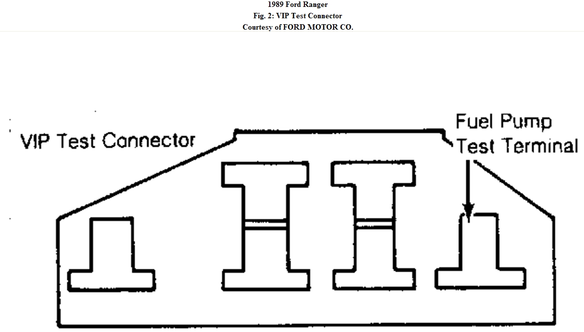
1. Check fuel tank(s) for adequate fuel supply. Check for fuel leaks at fittings and lines. Install
jumper lead to fuel pump test terminal of VIP test connector. See Fig. 2. Use a test lead long
enough to reach under vehicle. Install fuel pressure gauge. Turn ignition switch to the "RUN"
position. Ground jumper lead and refer to FUEL PUMP PRESSURE WITH ENGINE
RUNNING table. If fuel pressure is within specification, go to step 5). If fuel pressure is not
within specification, go to step 2).
Fig. 2: VIP Test Connector
CAUTION: Fuel system is under pressure. Before removing any fuel lines,
depressurize fuel system. See DEPRESSURIZING FUEL SYSTEM.
CAUTION: Fuel system is under pressure. Before removing any fuel lines,
depressurize fuel system. See DEPRESSURIZING FUEL SYSTEM.
FUEL PUMP PRESSURE WITH ENGINE RUNNING
2. If fuel pressure is low but greater than 3 psi (indicates pump is working), go to step 3). If not,
go to step 4).
3. Check fuel system for plugged fuel filter or restricted fuel lines. Check for low voltage at the
fuel pump (voltage should be with.5 volt of battery voltage). Disconnect fuel return line. If
fuel is returning, replace pressure regulator. If filters are clear, voltage correct and no fuel
return, replace fuel pump.
4. Ensure that battery voltage and ground are present at fuel pump connector. If circuits and
voltages are correct, replace fuel pump.
5. Disconnect grounded test lead and note fuel pressure. Fuel pressure should remain within 3 psi
for 3 minutes after disconnecting test lead. If fuel pressure holds, go to step 7). If not, go to
step 6).
6. Inspect for fuel leaks. If no leaks are found, disconnect and plug fuel return line. Ground test
lead and raise pressure to normal level. If fuel pressure now holds, replace pressure regulator.
If not, replace fuel pump.
7. Disconnect vacuum to fuel pressure regulator and start engine. Fuel pressure should be within
specification of FUEL PRESSURE WITH ENGINE RUNNING table. If fuel pressure is
correct, go to step 9). If fuel pressure is not, go to step 8).
8. If fuel pressure is low, check fuel filter, fuel pressure regulator adjustment, fuel line restrictions
or voltage to fuel pump. If all systems are normal, replace fuel pump.
9. With engine idling and fuel pressure regulator vacuum hose disconnected, measure fuel
pressure. Accelerate rapidly and note fuel pressure. If fuel pressure drops more than 5 psi,
repeat step 8). If fuel pressure does not drop, fuel system is operating correctly.
LOW PRESSURE IN-TANK FUEL PUMP
1. Check fuel tank(s) for adequate fuel supply. Check for fuel leaks at fittings and lines. Install
jumper lead to fuel pump test terminal of VIP test connector. See Fig. 2. Use a test lead long
enough to reach under vehicle. Raise vehicle and ground test lead. Use a stethoscope and listen
for pump operation. If low pressure pump is running, go to step 2). If not, go to step 3).
2. Disconnect test lead from ground. Remove reservoir inlet hose at reservoir. Place fuel hose in
one quart calibrated container and ground test lead for 5 seconds. Fuel level should be at least 6
Application Pressure
2.3L
30-45 psi
2.9L
30-45 psi
3.0L
30-45 psi
4.9L
45-60 psi
5.0L
30-45 psi
5.8L
30-45 psi
7.5L
30-45 psi
CAUTION: Fuel system is under pressure. Before removing and fuel lines,
depressurize fuel system. See DEPRESSURIZING FUEL SYSTEM.
Ounces. If fuel pump volume is correct, fuel pump is okay. If not, restrict fuel line momentarily
to prime pump. If no flow develops, check for blocked fuel lines. If no blockage is found, replace pump.
3. If pump does not run, inspect all electrical connections. Check inertia switch and fuel pump
relay for operation. If high pressure pump runs, but low pressure pump does not and voltage is
present, replace low pressure fuel pump.
REMOVAL & INSTALLATION
Images (Click to make bigger)
Monday, February 14th, 2011 AT 11:57 PM