You didnt give the engine size and 8th letter of VIN but here's how on all sixes. CMP Synchonizer must be used!
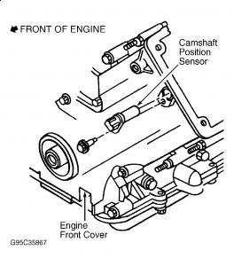
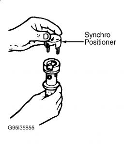
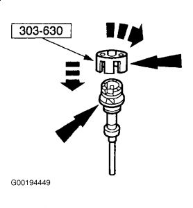
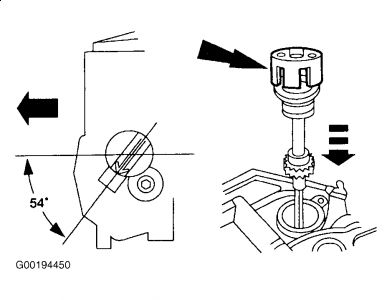
CMP SYNCHRONIZER Removal (3.0L VIN U & 2) 1. Disconnect negative battery cable. Note position of CMP sensor electrical connector. Remove CMP sensor. See REMOVAL & INSTALLATION (3.0L VIN U & 2) under CAMSHAFT POSITION SENSOR (CMP). Before removing CMP synchronizer assembly, set piston No. 1 to Top Dead Center (TDC) of compression stroke. 2. Apply reference marks on CMP synchronizer assembly and engine. Remove CMP synchronizer assembly hold-down bolt and clamp. Remove CMP synchronizer assembly. Oil pump drive shaft may come out with synchronizer. If so, retrieve oil pump driveshaft before proceeding. Installation (3.0L VIN U & 2) 1. Install Synchro Positioner (303-589) on CMP synchronizer assembly (CMP sensor removed). See Fig. 2. Turn CMP synchronizer shaft clockwise until tool boss engages with notch in CMP synchronizer assembly. Tool should fit squarely in top of CMP synchronizer assembly. 2. Ensure piston No. 1 is in TDC position on compression stroke. Install oil pump drive shaft in CMP synchronizer assembly. Lubricate CMP synchronizer gear with engine oil. Arrow on synchro positioner will rotate clockwise until CMP synchronizer is fully seated. Insert CMP synchronizer assembly into engine. 3. When installed, synchro positioner should point approximately 38 degrees from centerline of engine. See Fig. 3. Install and tighten CMP synchronizer hold-down clamp bolt. If synchro positioner is not pointing in correct direction, remove CMP synchronizer assembly and return to step 1. If CMP synchronizer is installed correctly, remove synchro positioner. 4. Install CMP sensor and tighten bolts to specification. See TORQUE SPECIFICATIONS. Connect CMP sensor harness connector and negative battery cable. CAUTION: DO NOT rotate crankshaft or camshaft during removal or installation of synchronizer or fuel system will become out of time with engine and may cause engine damage. NOTE: After installation, do not loosen the synchronizer bolt and rotate the synchronizer assembly. The synchronizer assembly is not adjustable. Do not loosen the synchronizer bolt after the alignment tool has been removed in order to align the CMP electrical connector for any reason. If the electrical connector is not in the correct position, the synchronizer assembly must be removed, the alignment tool and the assembly reinstalled, if the engine has not been rotated from Top Dead Center (TDC) of the compression stroke on the No. 1 cylinder. NOTE: Coat CMP synchronizer gear with engine oil prior to installation. Failure to do so, may result in gear failure. Fig. 2: Installing Synchro Positioner On Synchronizer Assembly (Typical) Courtesy of FORD MOTOR CO. Fig. 3: Installing CMP Synchronizer (Except 3.0L VIN S) Courtesy of FORD MOTOR CO. Removal (3.8L) 1. Rotate crankshaft until No. 1 cylinder is at TDC of compression stroke. Disconnect negative battery cable. Remove the EGR valve to exhaust manifold tube. 2. Note position of CMP sensor electrical connector. Remove CMP sensor. See REMOVAL & INSTALLATION (3.8L) under CAMSHAFT POSITION SENSOR (CMP). 3. Remove the camshaft synchronizer bolt. Remove camshaft synchronizer from engine block. Installation (3.8L) 1. Install Synchro Positioning Tool (303-630) on the camshaft synchronizer by rotating the tool until it engages the notch in the camshaft synchronizer housing and the armature. See Fig. 4. 2. Install camshaft synchronizer housing assembly so the arrow on the Install Synchro Positioning Tool (303-630) is 54 degrees from centerline of the engine. See Fig. 5. 3. Install and tighten synchronizer hold down bolt. See TORQUE SPECIFICATIONS. 4. Remove Synchro Positioning Tool (303-630). Install CMP sensor to camshaft synchronizer. See REMOVAL & INSTALLATION (3.8L) under CAMSHAFT POSITION SENSOR (CMP). Install the EGR valve to exhaust manifold tube. Connect the battery ground cable. Fig. 4: Installing Synchro Positioning Tool On Camshaft Synchronizer Assembly Courtesy of FORD MOTOR CO. Fig. 5: Aligning Camshaft Synchronizer Assembly NOTE: Oil pump driveshaft might come out with the camshaft synchronizer. If so, retrieve the oil pump driveshaft before proceeding. CAUTION: DO NOT rotate crankshaft while synchronizer is removed from engine. NOTE: After installation, do not loosen the synchronizer bolt and rotate the synchronizer assembly. The synchronizer assembly is not adjustable. Do not loosen the synchronizer bolt after the alignment tool has been removed in order to align the CMP electrical connector for any reason. If the electrical connector is not in the correct position, the synchronizer assembly must be removed, the alignment tool and the assembly reinstalled if the engine has not been rotated from Top Dead Center (TDC) of the compression stroke on the No. 1 cylinder. Courtesy of FORD MOTOR CO. CRANKSHAFT POSITION (CKP) SENSOR Removal & Installation (2.0L SOHC - VIN P) CKP sensor is located at rear of engine block, near flywheel. Disconnect negative battery cable. Raise and support vehicle. On Escort, remove splash shield. On all models, disconnect wiring from CKP sensor. Remove mounting bolts and CKP sensor. To install, reverse removal procedure. Removal & Installation (2.0L DOHC - VIN Z & 3) CKP sensor is located at rear of engine block, near flywheel. On Escort, removal of exhaust manifold may be necessary to remove sensor. See appropriate article in ENGINES. On all models, disconnect wiring from sensor. Remove sensor mounting bolt. Remove sensor. To install, reverse removal procedure. Removal & Installation (2.5L) CKP sensor is located on front cover near crankshaft pulley. Disconnect negative battery cable. Raise and support vehicle. Remove splash shield from right side of engine compartment. Remove electrical connector from CKP sensor. Remove mounting bolt and CKP sensor. To install, reverse removal procedure. Removal & Installation (All Others) 1. CKP sensor is located on front cover near crankshaft pulley. Disconnect negative battery cable. Remove serpentine drive belt and A/C compressor if necessary. Raise and support vehicle. Remove splash shields as necessary to access CKP sensor. 2. Disconnect wiring from CKP sensor. Remove CKP sensor bolt and CKP sensor. To install, reverse removal procedure. Tighten CKP sensor bolt to specification. See TORQUE SPECIFICATIONS. Evacuate and recharge A/C system as necessary.
Jul 12, 2009 at 11:31 AM