TESTS W/CODES - 5.0L -1996 Ford Bronco
Page 1 of 6
CIRCUIT TEST HX - EVAPORATIVE EMISSION (EVAP) MONITOR & SYSTEM
Diagnostic Aids
Perform this test when instructed during QUICK TEST or if directed by other test procedures. This test is used to diagnose the following:
� � � Leaks in fuel tank, filler cap or vapor hoses.
� � � Faulty Canister Vent (CV) solenoid.
� � � Faulty Fuel Tank Pressure (FTP) Sensor.
� � � Faulty fuel vapor valve.
� � � Faulty fuel vapor control valve (if equipped).
� � � Faulty carbon canister.
� � � Wiring harness circuits (CV, FTP, PWR GND, VMV, VPWR and VREF).
� � � Faulty PCM.
Fig. 65: FTP Connector & Test Circuit
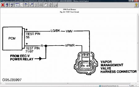
Fig. 66: VMV Connector & Test Circuit
1) Continuous Memory DTC P0442 Or P1442 Turn ignition off. Ensure fuel fill cap is correctly installed. Ensure cap is not damaged or excessively worn. Service or replace as necessary and verify symptom is repaired. If fuel fill cap is okay, go to next step. 2) Leave ignition off. Check all fuel vapor hoses for damage or restrictions. Ensure hose connections are tight. Service or replace as necessary and verify symptom is repaired. If fuel vapor hoses are okay, go to step 61).
NOTE: A break in step numbering sequence occurs at this point. Procedure skips from step 2) to step 6). No test procedures have been omitted.
6) Continuous Memory DTC P0443 Perform QUICK TEST . If DTC P0443 is present in Continuous Memory only, go to step 12). If DTC P0443 is present in KOEO or KOER SELF-TEST , go to next step. 7) DTC P0443: Check VPWR Circuit Voltage Turn ignition off. Disconnect Vapor Management Valve (VMV) wiring harness connector. Turn ignition on. Measure voltage between VPWR terminal of VMV wiring harness connector and battery ground. If voltage is 10.5 volts or more, go to next step. If voltage is less than 10.5 volts, repair open in VPWR circuit and repeat QUICK TEST . 8) Check VMV Resistance Turn ignition off. Leave VMV wiring harness connector disconnected. Measure resistance between CANP solenoid or VMV terminals. If resistance is 30-36 ohms, go to next step. If resistance is not as specified, replace VMV and repeat QUICK TEST . 9) Check VMV Circuit Continuity Leave ignition off and VMV wiring harness connector disconnected. Disconnect PCM wiring harness connector. Inspect pins for damage and repair as necessary. Install EEC-V Breakout Box (014-000950), leaving PCM disconnected. Measure resistance between test pin No. 56 at breakout box and VMV terminal of VMV wiring harness
8/16/2008
TESTS W/CODES - 5.0L -1996 Ford Bronco
Page 2 of 6
connector. If resistance is less than 5 ohms, go to next step. If resistance 5 ohms or more, repair open circuit and repeat QUICK TEST . 10) Check Circuit For Short To PWR GND Leave ignition off and VMV wiring harness connector disconnected. Disconnect scan tester from DLC (if applicable). Measure resistance between test pin No. 56 (VMV) and test pins No. 24 and 103. If each resistance is more than 10,000 ohms, go to next step. If resistance is 10,000 ohms or less, repair VMV circuit short to PWR GND circuit. Clear PCM memory and repeat QUICK TEST . 11) Leave ignition off and VMV disconnected. Turn ignition on. Measure voltage between breakout box test pin No. 56 and test pins No. 51 and 103. If voltage is greater than 10.5 volts, repair VMV circuit short to VPWR and repeat QUICK TEST . If voltage is 10.5 volts or less, replace PCM and repeat QUICK TEST . 12) Wiggle Test VMV & Harness Turn ignition off. Disconnect PCM wiring harness connector. Inspect pins for damage and repair as necessary. Install EEC-V Breakout Box (014-000950), leaving PCM disconnected. Using DVOM, measure resistance between test pin No. 56 (VMV) and test pins No. 71 and 97. Observe DVOM for indication of fault while shaking and bending VMV wiring harness and connector. A fault will be indicated by resistance measurement of less than 30 ohms or more than 36 ohms. Tap lightly on VMV to simulate road shock. If fault is indicated, isolate and repair as necessary. If no fault is indicated, see CIRCUIT TEST Z. 13) Continuous Memory DTC P0446 Turn ignition off. Remove fuel fill cap. Connect scan tester to DLC. Turn ignition on. Using scan tester, access FTP V PID. Record FTP T PID voltage. Install fuel fill cap to first click. If FTP T PID voltage is 2.37-2.87 volts, go to step 15). If FTP T PID voltage is not 2.37-2.87 volts, go to next step. 14) Check VREF At FTP Connector Turn ignition off. Disconnect FTP wiring harness connector. Turn ignition on. Measure voltage between VREF terminal and SIG RTN terminal at wiring harness connector. If voltage is 4-6 volts, replace FTP sensor and repeat QUICK TEST . If voltage is not 4-6 volts, go to CIRCUIT TEST C. 15) Check Carbon Canister Check for restrictions at carbon canister atmosphere vent port. Check for restrictions in purge air inlet tube (large diameter hose) between CV solenoid and atmosphere. Repair or replace as necessary. If no faults are found, go to next step. 16) Check CV Solenoid Filter Port Disconnect purge air inlet tube (large diameter hose) from CV solenoid. If vehicle is not equipped with purge air inlet tube, go to next step. Locate opposite end of tube (in fuel filter housing). Drop a 3/8" ball bearing into tube. If ball bearing passes through tube, go to next step. If ball bearing does not pass through tube, service or replace tube as necessary and repeat QUICK TEST . 17) Check CV Solenoid Mechanical Operation Remove CV solenoid hose. Connect vacuum pump to solenoid. Using vacuum pump, apply 16 in. Hg to solenoid. If vacuum is held for one minute, replace solenoid and repeat QUICK TEST . If vacuum is not held for one minute, go to next step. 18) DTC P0446 Turn ignition off. Connect scan tester to DLC. Turn ignition on. Using tester, access EVAPCVF PID. If scan tester indicates YES, go to next step. If scan tester does not indicate YES, go to step 21). 19) Check CV Solenoid Resistance Turn ignition off. Disconnect CV solenoid wiring harness connector. Measure resistance between CV and VPWR terminal at solenoid. If resistance is less than 45 ohms, replace CV solenoid and repeat QUICK TEST . If resistance is 45 ohms or more, go to next step. 20) Check Circuit For Short To PWR GND Leave ignition off. Disconnect PCM wiring harness connector. Inspect pins for damage and repair as necessary. Install EEC-V Breakout Box (014-000950), leaving PCM disconnected. Measure resistance between test pin No. 67 (CV) and test
8/16/2008
TESTS W/CODES - 5.0L -1996 Ford Bronco
Page 3 of 6
pins No. 51 and 103. If each resistance is more than 10,000 ohms, replace PCM and repeat QUICK TEST . If resistance is 10,000 ohms or less, repair CV circuit short to PWR GND circuit. Clear PCM memory and repeat QUICK TEST . 21) Wiggle Test CV Solenoid & Harness Turn ignition on. Using scan tester, access EVAPCVF PID. Observe EVAPCVF PID for indication of fault while shaking and bending CV solenoid wiring harness and connector. A fault will be indicated by a change in EVAPCVF PID voltage. Tap lightly on CV solenoid to simulate road shock. If fault is indicated, isolate and repair as necessary. If no fault is indicated, go to CIRCUIT TEST Z. 22) DTC P0452 Turn ignition off. Connect scan tester to DLC. Check FTP wiring harness connector for damage or fuel contamination. Repair or replace if necessary. If connector is okay, go to next step. 23) Verify FTP Signal Voltage Leave ignition off. Connect scan tester to DLC. Turn ignition on. Using scan tester, access FTP V PID. If FTP V PID is less than 0.22 volts, go to next step. If FTP V PID is 0.22 volts or more, go to step 27). 24) Induce Opposite FTP Signal Leave ignition off. Disconnect FTP wiring harness connector. Connect jumper wire between FTP terminal and VREF terminal at connector. Turn ignition on. Using scan tester, access FTP V PID. If scan tester error occurs, go to next step. If FTP V PID is 4-6 volts, replace FTP and repeat QUICK TEST . If FTP V PID is not 4-6 volts, remove jumper wire and go to next step. 25) Check VREF At FTP Connector Leave ignition off. Disconnect FTP wiring harness connector. Connect jumper wire between FTP terminal and VREF terminal at connector. Turn ignition on. Using scan tester, access FTP V PID. If scan tester error occurs, go to next step. If FTP V PID is 4-6 volts, replace FTP and repeat QUICK TEST . If FTP V PID is not 4-6 volts, remove jumper wire and go to next step. 26) Check Circuit For Short To PWR GND Or SIG RTN Leave ignition off and FTP disconnected. Disconnect PCM wiring harness connector. Inspect pins for damage and repair as necessary. Install EEC-V Breakout Box (014-000950), leaving PCM disconnected. Disconnect scan tester from DLC. Measure resistance between test pin No. 62 (FTP) and test pins No. 51, 91 and 103. If each resistance more than 10,000 ohms, replace PCM, repeat QUICK TEST . If resistance is 10,000 ohms or less, repair FTP circuit short to SIG RTN or PWR GND circuit. Clear PCM memory and repeat QUICK TEST . 27) Wiggle Test CV Solenoid & Harness Turn ignition on. Using scan tester, access FTP V PID. Observe FTP V PID for indication of fault while shaking and bending FTP sensor wiring harness and connector. A fault will be indicated by a change in FTP V PID voltage. Tap lightly on FTP sensor to simulate road shock. If fault is indicated, isolate and repair as necessary. If no fault is indicated, go to CIRCUIT TEST Z. 28) DTC P0453 Turn ignition off. Connect scan tester to DLC. Turn ignition on. Using tester, access FTP V PID. If FTP V PID more than 4.5 volts, go to next step. If FTP V PID 4.5 volts or less, go to step 37). 29) Check FTP Signal For Short To Power Leave ignition off. Disconnect FTP wiring harness connector. Turn ignition on. Measure voltage between negative battery terminal and FTP terminal at wiring harness connector. If voltage is 10.5 volts or more, go to next step. If voltage is less than 10.5 volts, go to step 31). 30) Check FTP Circuit For Short To VPWR Leave FTP disconnected. Disconnect PCM wiring harness connector. Inspect pins for damage and repair as necessary. Install EEC-V Breakout Box (014-000950), leaving PCM disconnected. Turn ignition on. Measure voltage between test pin No. 62 (FTP) and test pins No. 51 and 103 at breakout box. If either voltage is less than 10.5 volts, replace PCM and repeat QUICK TEST . If all voltages are 10.5 volts or more, repair FTP circuit
8/16/2008
TESTS W/CODES - 5.0L -1996 Ford Bronco
Page 4 of 6
short to VPWR. Clear PCM memory and repeat QUICK TEST . 31) Induce Opposite FTP Signal Turn ignition off. Leave FTP wiring harness connector disconnected. Connect jumper wire between FTP terminal and SIG RTN terminal at connector. Turn ignition on. Using scan tester, access FTP V PID. If scan tester error occurs, go to step 36). If FTP V PID is less than 0.1 volt, go to next step. If FTP V PID is 0.1 volts or more, go to step 34). 32) Check VREF At FTP Connector Leave ignition off. Disconnect FTP wiring harness connector. Measure voltage between SIG RTN terminal and VREF terminal at wiring harness connector. If voltage is 4-6 volts, go to next step. If voltage is not 4-6 volts, go to CIRCUIT TEST C. 33) Check FTP Circuit For Short To VREF Leave ignition off and FTP disconnected. Disconnect PCM wiring harness connector. Inspect pins for damage and repair as necessary. Install EEC-V Breakout Box (014-000950), leaving PCM disconnected. Disconnect scan tester from DLC. Measure resistance between test pins No. 62 (FTP) and 90 (VREF) at breakout box. If resistance is more than 10,000 ohms, replace FTP sensor and repeat QUICK TEST . If resistance is 10,000 ohms or less, repair FTP circuit short to VREF. Clear PCM memory and repeat QUICK TEST . 34) Check FTP Circuit Continuity Leave ignition off and FTP disconnected. Disconnect PCM wiring harness connector. Inspect pins for damage and repair as necessary. Install EEC-V Breakout Box (014-000950), leaving PCM disconnected. Disconnect scan tester from DLC. Measure resistance between test pin No. 62 (FTP) and FTP terminal at FTP wiring harness connector. If resistance is less than 5 ohms, go to next step. If resistance is 5 ohms or more, repair open in FTP circuit. Clear PCM memory and repeat QUICK TEST . 35) Check SIG RTN Circuit Continuity Leave ignition off and FTP disconnected. Measure resistance between test pin No. 91 and SIG RTN terminal at FTP wiring harness connector. If resistance is less than 5 ohms, replace PCM and repeat QUICK TEST . If resistance is 5 ohms or more, repair open in SIG RTN circuit. Clear PCM memory and repeat QUICK TEST . 36) Check FTP Circuit For Short To VREF Leave ignition off and FTP disconnected. Disconnect PCM wiring harness connector. Inspect pins for damage and repair as necessary. Install EEC-V Breakout Box (014-000950), leaving PCM disconnected. Measure resistance between test pins No. 62 (FTP) and 90 (VREF) at breakout box. If resistance is more than 10,000 ohms, replace PCM and repeat QUICK TEST . If resistance is 10,000 ohms or less, repair FTP circuit short to VREF. Clear PCM memory and repeat QUICK TEST . 37) Wiggle Test CV Solenoid & Harness Turn ignition on. Using scan tester, access FTP V PID. Observe FTP V PID for indication of fault while shaking and bending FTP sensor wiring harness and connector. A fault will be indicated by a change in FTP V PID voltage. Tap lightly on FTP sensor to simulate road shock. If fault is indicated, isolate and repair as necessary. If no fault is indicated, go to CIRCUIT TEST Z.
NOTE: A break in step numbering sequence occurs at this point. Procedure skips from step 37) to step 40). No test procedures have been omitted.
40) Continuous Memory P0455 Or P1455 Turn ignition off. Ensure fuel fill cap is correctly installed and in good condition. Check carbon canister for damage. Check fuel vapor hoses for correct routing. Check fuel tank and fill pipe for damage. Repair or replace as necessary and go to step 61). If no faults are present, go to next step. 41) Check System Pressure Turn ignition off. Remove fuel fill cap. Disconnect and plug fuel
8/16/2008
TESTS W/CODES - 5.0L -1996 Ford Bronco
Page 5 of 6
vapor hose at VMV. Connect scan tester to DLC. Using scan tester, access Output Test Mode and select All Off mode. Turn ignition on. Using Evaporative Emission System Tester (Rotunda 134 00056), pressurize evaporative system at 14 in. Hg. (if evaporative emission system tester is not available, go to step 47). If system holds vacuum for 2 minutes, go to step 43). If system does not hold vacuum for 2 minutes, go to next step. 42) Leave ignition on and evaporative emission system pressurized. Using scan tester, access FTP V PID. If FTP V PID is 4.42-4.78 volts, go to next step. If voltage is not as specified, replace FTP sensor and go to step 61). 43) Leave ignition on and evaporative emission system pressurized. Close purge air inlet tube at CV solenoid port. If system does not hold vacuum for 2 minutes, go to step 45). If system holds vacuum for 2 minutes, go to next step. 44) Check FTP Signal For Short To Power Leave ignition off. Disconnect CV solenoid wiring harness connector. Disconnect PCM wiring harness connector. Inspect pins for damage and repair as necessary. Install EEC-V Breakout Box (014-000950). Connect PCM to breakout box. Turn ignition on. Measure voltage between negative battery terminal and VPWR terminal at CV solenoid wiring harness connector. If voltage is 10.5 volts or more, replace CV solenoid and go to step 61). If voltage is less than 10.5 volts, repair open in VPWR circuit and go to step 61). 45) Check For Leaks Using Ultra Sonic Leak Detector Leave ignition on and CV solenoid wiring harness connector disconnected. Using ultra sonic earphones, pass probe over fuel vapor hoses and connections. If sudden audible change is detected (indicating leak), isolate and repair as necessary. If leak is not detected, release system pressure and go to next step. 46) Check Fuel Vapor Hose Leave ignition on and CV solenoid wiring harness connector disconnected. Remove and plug fuel vapor hose from carbon canister at VMV. Using evaporative emission system tester, pressurize evaporative system at 14 in. Hg. When pressure stabilizes, remove plug from fuel vapor hose. If pressure drops immediately, install fuel fill cap and tighten to first click. Go to next step. If pressure does not drop immediately, isolate restriction in system and repair as necessary. Reconnect all components and go to step 61). 47) Check Intake Manifold Vacuum At VMV Leave ignition off. Connect VMV wiring harness connector. Disconnect hoses from VMV at intake manifold. Start engine and allow to idle. Check for vacuum at intake manifold. If vacuum is present, go to next step. If vacuum is not present, isolate fault. Repair as necessary and go to step 61). 48) Check VMV Ability To Hold Vacuum Leave ignition off. Connect vacuum pump to disconnected end of VMV hose. Using vacuum pump, apply 16 in. Hg. If vacuum bleeds off immediately, go to next step. If vacuum does not bleed off immediately, isolate hose restriction and repair as necessary. Go to step 61). 49) Check VMV Turn ignition off. Reconnect VMV wiring harness connector. Disconnect VMV fuel vapor hose from intake manifold port at VMV. Attach vacuum pump with gauge to intake manifold port at VMV. Using vacuum pump, apply 16 in. Hg to VMV. If vacuum bleeds off immediately, go to next step. If vacuum is not bled off immediately, replace VMV and go to step 61). 50) Check VPWR Circuit Voltage Turn ignition off. Connect PCM to breakout box. Disconnect VMV wiring harness connector. Turn ignition on. Measure voltage between VPWR terminal of VMV wiring harness connector and battery ground. If voltage is 10.5 volts or more, go to next step. If voltage less than 10.5 volts, repair open in VPWR circuit, repeat QUICK TEST . 51) Check VMV Turn ignition off. Ensure PCM is connected to breakout box. Reconnect VMV vacuum input hose. Disconnect fuel vapor to carbon canister hose. Connect vacuum gauge to vacuum port. Start engine and allow to idle for 5 minutes. Vacuum gauge should read zero. Connect jumper wire between test pin No. 56 (VMV) and test pin No. 51 or 103 at breakout box.
8/16/2008
TESTS W/CODES - 5.0L -1996 Ford Bronco
Page 6 of 6
Vacuum should be about engine manifold vacuum. If vacuum is not as specified, replace VMV and go to step 61). If vacuum is as specified, remove vacuum gauge and jumper wire. Go to next step. 52) Check CV Circuit Continuity Turn ignition off. Disconnect CV solenoid wiring harness connector. Disconnect PCM from breakout box. Measure resistance between test pin No. 67 at breakout box and CV terminal at CV solenoid wiring harness connector. If resistance is less than 5 ohms, go to next step. If resistance is 5 ohms or more, repair open in CV circuit. Clear PCM memory and repeat QUICK TEST . 53) Check CV Circuit For Short To Power Turn ignition on. Measure voltage between test pin No. 67 and test pin No. 51 or 103 at breakout box. If voltage is more than 10.5 volts, repair CV circuit short to VPWR. If voltage is 10.5 volts or less, go to step 61).
NOTE: A break in step numbering sequence occurs at this point. Procedure skips from step 53) to step 56). No test procedures have been omitted.
56) DTC P1450 Or P1452 Turn ignition off. Remove input vacuum hose from VMV. Connect vacuum pump to VMV. Using vacuum pump, apply 10 in. Hg to solenoid. If vacuum is held for one minute, replace VMV and go to step 61). If vacuum is not held for one minute, remove vacuum pump and go to next step. 57) Check VREF Connectors Leave ignition off. Check VREF circuit terminal at FTP sensor and PCM. If terminal connectors are okay, go to next step. If terminal connectors are faulty, go to step 61). 58) Check CV Circuit Continuity Turn ignition off. Disconnect FTP solenoid wiring harness connector. Disconnect PCM wiring harness connector. Inspect pins for damage and repair as necessary. Install EEC-V Breakout Box (014-000950), leaving PCM disconnected. Measure resistance between test pin No. 90 at breakout box and VREF terminal at FTP sensor wiring harness connector. If resistance is less than 5 ohms, replace FTP sensor and go to next step. If resistance is 5 ohms or more, repair open in VREF circuit and go to next step.
NOTE: A break in step numbering sequence occurs at this point. Procedure skips from step 58) to step 61). No test procedures have been omitted.
61) Verify EVAP System Repair With ignition on and scan tester connected to DLC, clear PCM memory. Start engine and allow to idle for at least 4 minutes. Drive vehicle 45-60 MPH in high gear for about 8 minutes. Drive vehicle in city traffic condition averaging 25-40 MPH. Ensure at least 5 stop with idle periods of 10 seconds or more. Accelerate vehicle to 45-60 MPH and operate in high gear for about 8 minutes. Stop vehicle and repeat QUICK TEST . If DTC P1000 is present, repeat this step. If any other DTCs are present, service as necessary. See DIAGNOSTIC TROUBLE CODE (DTC) REFERENCE CHART . If no DTCs are present, testing is
complete.
8/16/2008
Saturday, August 16th, 2008 AT 7:27 PM