EVAP vent valve diagram?

Tiny
KROMAN14
  • MEMBER
  • 2011 FORD EXPLORER
  • 3.5L
  • V6
  • 4WD
  • AUTOMATIC
  • 175,000 MILES
I'm working in my vehicle listed above because it has a evap code an I checked the evap vent valve with a scan tool that can activate solenoids and it did not work. I believe there is a short or open in the wire somewhere. I need the wire diagram to trace the wire to the PCM. I checked one of the terminals at the valve and there is 12 volts.
Sunday, June 15th, 2025 AT 10:20 AM

4 Replies

Tiny
AL514
  • MECHANIC
  • 5,344 POSTS
Hello, do you have 12volts on both wires with it plugged in and back probing the connector? I'll pull the diagrams you need, but checking for 12volts on both wires plugged in verifies that the valve is not open circuit inside for one and also verifies the control wire is not shorted to ground. With the vent valve not activated by the PCM you should read power coming through the solenoid.
There are also two connectors in between the solenoid and the PCM.
Was this
answer
helpful?
Yes
No
Sunday, June 15th, 2025 AT 11:13 AM
Tiny
AL514
  • MECHANIC
  • 5,344 POSTS
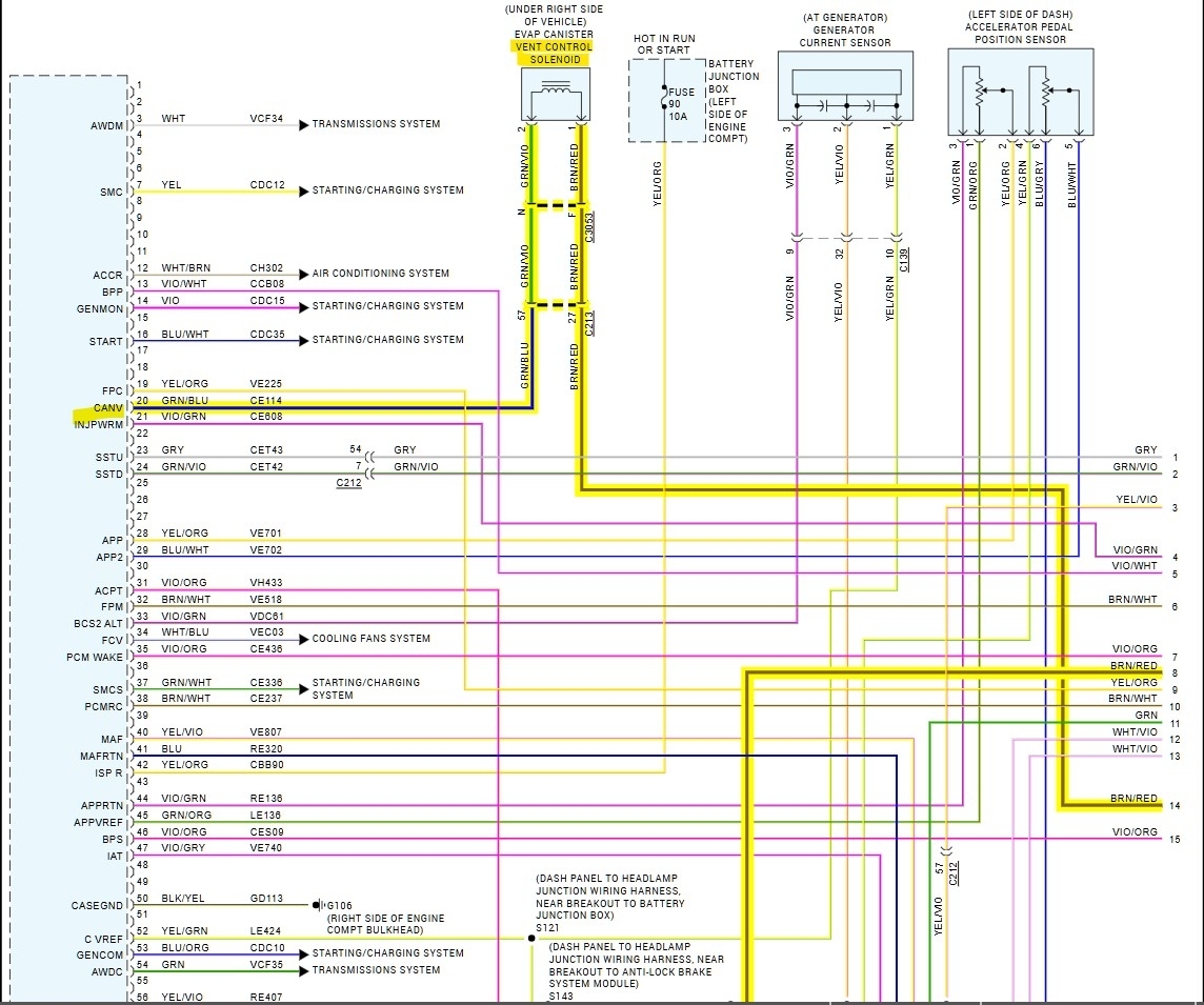
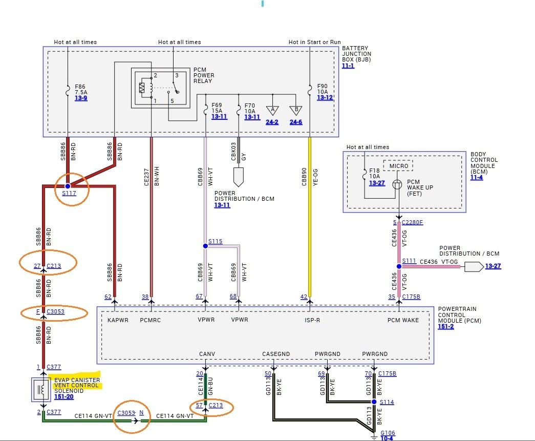
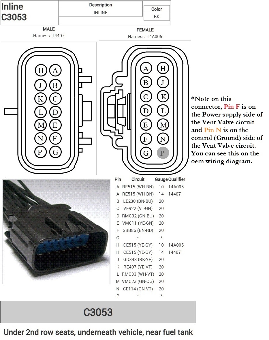
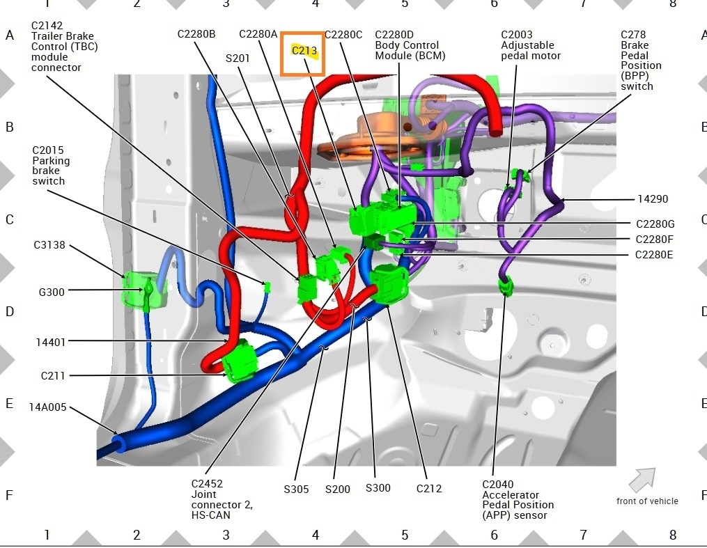
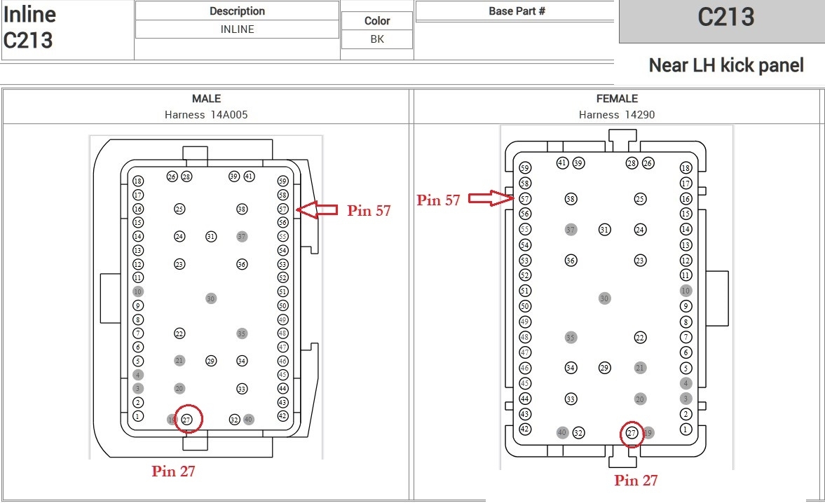
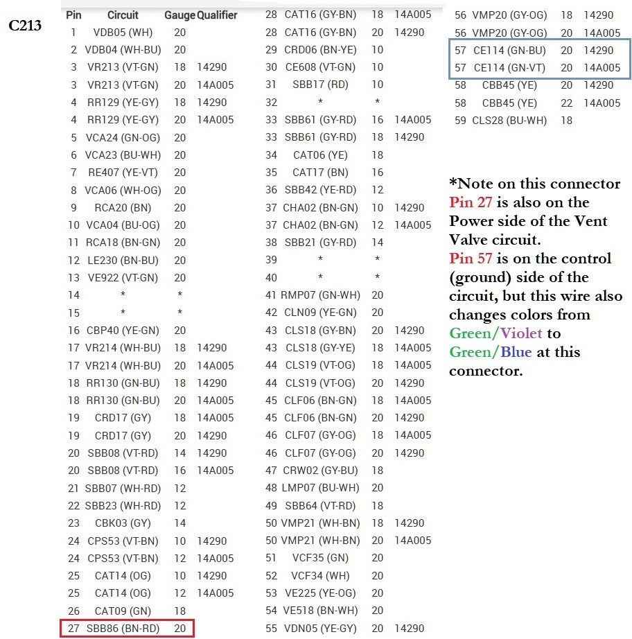
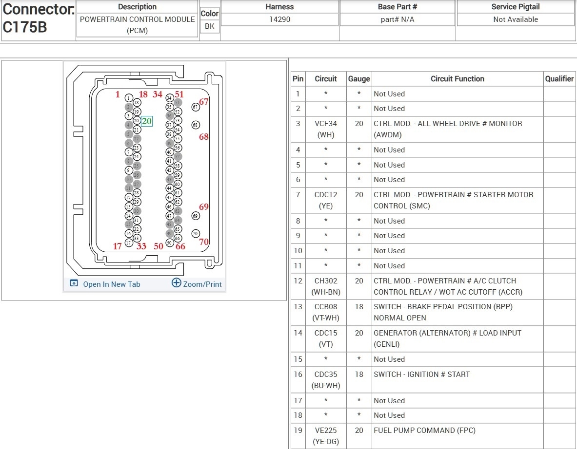
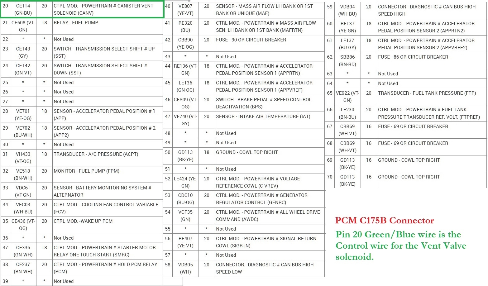
Strangely enough I already had the Vent valve wiring diagrams and connector locations from another 2011 Explorer, same issue, so the 1st diagram is the aftermarket wiring and the 2nd is the OEM Ford wiring, Notice the control wire changes colors after the 2nd connector. So Green/Violet to Green/Blue at the PCM. Going from the Vent valve the first connector is C3053 pin N is the control wire to the PCM, and pin E is the power wire in this same connector. The next one is C213 (diagrams 5, 6, 7) notice it is located behind the driver's side left kick panel, where your left foot would be. This is where it changes colors going in on pin 57 a Green/Violet wire on one side of the connector and coming out the other side pin 57 but a Green/Blue wire which then goes to the PCM connector C175B pin 20 (diagrams 8, 9).
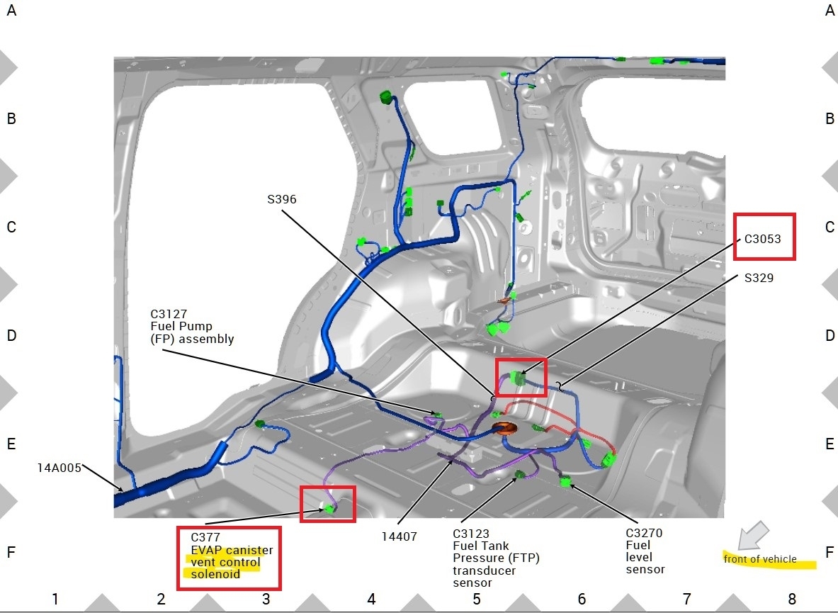
So, there could be an issue at the C3053 connector which is under the 2nd row seats but under the vehicle (diagram 4) which is more likely to be affected by the elements. So, I would check that connector first then work your way forward. Or just go right to the PCM connector, with the key On you should read 12volts if the vent solenoid is inactive. And zero volts if the PCM is grounding the circuit. But you can do the same test right at the Vent solenoid, with it plugged in, if you bi-directionally control it On, the Green/Violet wire should go to ground.
Was this
answer
helpful?
Yes
No
Sunday, June 15th, 2025 AT 12:02 PM
Tiny
KROMAN14
  • MEMBER
  • 3 POSTS
Thanks for the response, I'll try to trace the other wire because I think it may be shorted or open. I'll get back to you.
Was this
answer
helpful?
Yes
No
Monday, June 16th, 2025 AT 5:25 AM
Tiny
AL514
  • MECHANIC
  • 5,344 POSTS
Okay, I would start with that connector C3053 first, being under the vehicles there's a good chance the connector is corroded, and if it's okay at least you can test there and know whether the issue is further up towards the front of the vehicle or back further. What you could do to simplify the process is go right to the connector behind the kick panel because both the power wire and control wire run through the C213 connector, you can unplug it and check across the two wires right there and you should read the resistance of the vent valve. You can do the same with the other connector C3053. Let us know what you find. This seems to be a common fault for this year, I don't remember if the last one was a broken wire or just a bad valve.
Was this
answer
helpful?
Yes
No
Monday, June 16th, 2025 AT 2:01 PM

Please login or register to post a reply.