Hi,
I'm not sure why, but I am not showing that code for this year make and model. I suspect it is referencing the ABS actuator solenoid valve. BY any chance, do you know the two or three-digit manufacturer code?
Here are the diagnostics for the ABS actuator solenoid. Let me know if this helps. Also, the attached pics correlate with the directions.
______________________
2006 Nissan-Datsun Sentra L4-1.8L (QG18DE)
ABS Actuator Solenoid Valve and Solenoid Valve Relay
Vehicle Brakes and Traction Control Antilock Brakes / Traction Control Systems Testing and Inspection Component Tests and General Diagnostics ABS Component Tests ABS Actuator Solenoid Valve and Solenoid Valve Relay
ABS ACTUATOR SOLENOID VALVE AND SOLENOID VALVE RELAY
ABS ACTUATOR SOLENOID VALVE AND SOLENOID VALVE RELAY
Diagnostic Procedure
Malfunction code No. 41, 42, 45, 46, 51, 52, 55, 56, 63
1. INSPECTION START
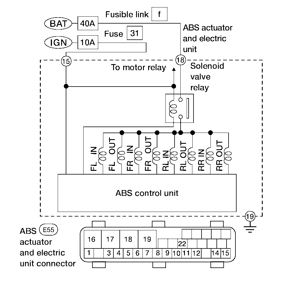
pic 1
Solenoid valve relay inspection
>> GO TO 2.
2. CHECK FUSIBLE LINK
Check 40A fusible link f.
Is fusible link OK?
YES >> GO TO 3.
NO >> GO TO 6.
3. CHECK CONNECTOR
1. Disconnect connector from ABS actuator and electric unit. Check terminals for damage or loose connection. Then reconnect connector.
2. Carry out self-diagnosis again.
Does warning lamp activate again?
YES >> GO TO 4.
NO >> Inspection End.
4. CHECK ABS ACTUATOR AND ELECTRIC UNIT GROUND CIRCUIT
Is ground circuit OK?
YES >> GO TO 5.
NO >> Repair harness or connector.
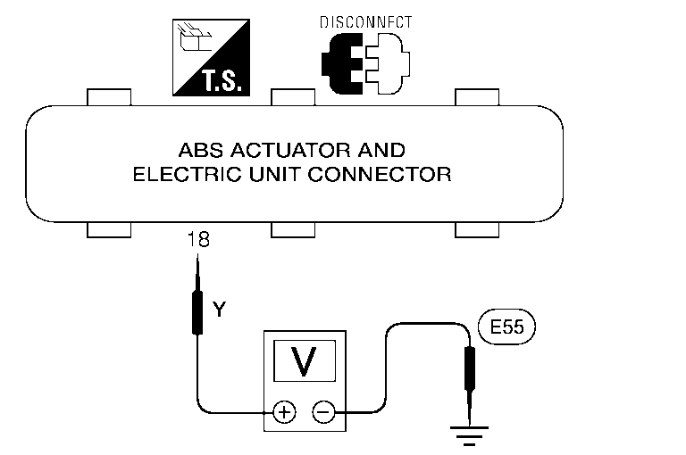
5. CHECK SOLENOID VALVE POWER SUPPLY CIRCUIT
1. Disconnect ABS actuator and electric unit connector.
pic 2
2. Check voltage between ABS actuator and electric unit connector E55 terminal 18 (Y) and ground.
Does battery voltage exist?
YES >> Replace ABS actuator and electric unit.
NO >> Check the following.
^ If NG, repair harness or connectors.
- Harness connector E55
- Harness for open between ABS actuator and electric unit and fusible link.
6. REPLACE FUSE
Replace 40A fusible link f.
Does the fusible link blow when ignition switch is turned ON?
YES >> GO TO 7.
NO >> Inspection End.
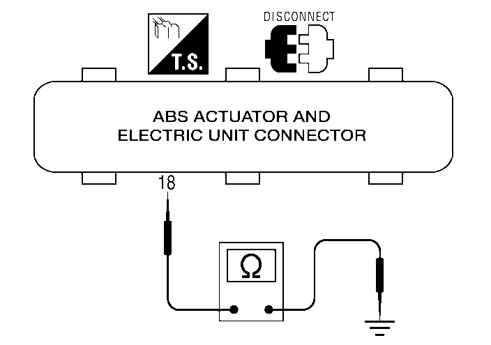
7. CHECK SOLENOID VALVE RELAY POWER SUPPLY CIRCUIT FOR SHORT
pic 3
1. Disconnect battery cable and ABS actuator and electric unit connector.
2. Check continuity between ABS actuator and electric unit connector E55 terminal 18 (Y) and ground.
Continuity should not exist.
Does continuity exist?
YES >> Check the following.
^ Harness connector E55
^ Harness for short between ABS actuator and electric unit and fusible link.
NO >> Replace ABS actuator and electric unit.
____________________________
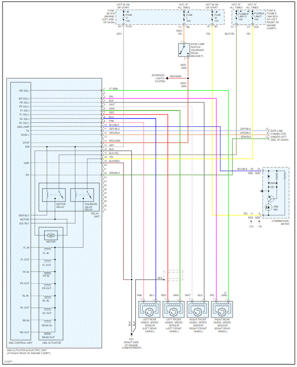
If you look at pic 4, it shows the entire wiring schematic related to the traction control and ABS.
Let me know if this helps.
Joe
Images (Click to enlarge)
Dec 4, 2020 at 7:02 PM