Engine codes that cannot be cleared, will not start?

Tiny
DAM LOUIS
  • MEMBER
  • 2003 SUBARU FORESTER
  • 2.0L
  • 4 CYL
  • 4WD
  • AUTOMATIC
  • 250,000 MILES
This vehicle was out of service for about 3 months while undergoing a transmission rebuild.

After the transmission was re-installed, the car refused to start. The engine cranks very well.

With the help of a couple of mechanics, the problem has been narrowed down to a crank no spark no start issue. The wiring has been checked thoroughly and all suspected faulty parts have been replaced.

We tried using scan tools to determine if there are any trouble codes.

Well, there are 14 trouble codes all starting with P0 that just cannot be cleared no matter what scan tool is used. They show up as soon as the ignition is turned on, before even cranking the engine

What could cause these codes to behave in that manner?

Thanks
Sunday, September 24th, 2023 AT 3:44 PM

8 Replies

Tiny
CARADIODOC
  • MECHANIC
  • 33,752 POSTS
First, you have to tell us the fault code numbers to help us know where to start. Second, clearing the codes doesn't make the causes go away. That's why they set again right away right after you erase them. Third, there's often some confusion about what the codes mean. Too many competent do-it-yourselfers think those codes tell you which part to replace, but in fact, they never say to replace a part or that one is bad. Fault codes only tell us which circuit or system needs further diagnosis, or the unacceptable operating condition. When a sensor or other part is referenced in a fault code, that part is actually the cause of that code about half of the time. Before spending our customers' money on a part, we have to rule out wiring and connector terminal problems, and mechanical problems associated with that part.

Next, when there's multiple codes that showed up at the same time, we start by looking for anything they have in common. That's especially true in this case where you have so many that occurred at the same time.

A good place to start is by looking up your code numbers here:

https://www.2carpros.com/trouble_codes/obd2

or list the numbers in your reply and I can interpret them for you.

As a hint, since major service was just completed, look for a hard-to-see electrical connector that got overlooked, a ground wire that didn't get bolted on, or a wire that became pinched between the engine and the transmission. Since the engine hasn't run yet, we can rule out heat-related things like a wire harness that fell down onto hot exhaust parts.

A lot of engine sensors run on a carefully regulated 5.0-volt supply from the Engine Computer. If that one feed wire is cut, shorted to ground, or simply has corrosion between a pair of mating terminals in a connector, it will cause all of those sensor circuits to set fault codes. It's common for crankshaft position sensors and camshaft position sensors to run on 5.0 volts too, but those don't generate a signal until the engine is rotating. Missing a signal from one or both of those sensors will result in no spark. Also, on many models, fault codes related to those missing signals often don't get detected right away, so we can't assume those sensors are working simply if there's no fault codes set related to them. On some models, right after you erase any fault code, then turn the ignition switch off, then back to "run", and read the codes again, those sensors will usually not have set a fault code again until after you crank the engine.

If you do have codes set relating to multiple engine sensors, but you can't find a cause, the easiest is to pick one of them and start with it. On most models the throttle position sensor is easy to reach. One very important detail to be aware of is for this type of problem, most of the voltage readings are only valid when taken while everything is plugged in and connected. There are times when that is not necessary, and there are times when using an old-style test light with an incandescent bulb inside can be more accurate than a voltmeter. The problem is test lights don't work well in 5.0-volt circuits, and they can load down a circuit much more than sensors, solenoids, and relays do. If you're working in sensor circuits, with a digital voltmeter, leave them plugged in, then use the meter's probe to back-probe through the rubber seal, alongside the wire. If the tip of the probe won't reach in far enough, you can stick in a stretched-out paper clip to touch the terminal, then take the reading on that paper clip.

Let me know what you find, then we'll figure out where to go next.
Was this
answer
helpful?
Yes
No
Sunday, September 24th, 2023 AT 5:34 PM
Tiny
DAM LOUIS
  • MEMBER
  • 6 POSTS
Thank you very much for your in-depth reply. We shall go over all connections again but in the meantime let me supply you with the scan codes as DTC codes as they show up on the scan tool. (Note tried 4 different scan tools - same result)

1/14 - P0123
2/14 - P0117
3/14 - P01510
4/14 - P01512
5/14 - P0514
6/14 - P0748
7/14 - P0743
8/14 - P0113
9/14 - P0108
10/14 - P01703
11/14 - P0778
12/14 - P0123
13/14 - P0117
14/14 - P0123
Was this
answer
helpful?
Yes
No
Sunday, September 24th, 2023 AT 6:09 PM
Tiny
DAM LOUIS
  • MEMBER
  • 6 POSTS
Do any of these codes look like they can be the source of a no spark no start condition?
Was this
answer
helpful?
Yes
No
Sunday, September 24th, 2023 AT 6:50 PM
Tiny
CARADIODOC
  • MECHANIC
  • 33,752 POSTS
P0123 - Throttle/Pedal Position Sensor/Switch A Circuit High Input

Two things can cause this code. By far the more common is a cut ground wire, corroded connector terminal, or corroded splice. Multiple sensors will share this ground wire, so depending on where the break is will determine how many sensors are affected and set fault codes.

The less common is a break in the sensor's signal circuit, and this one can defy logic. During normal operation, there's mechanical stops inside the sensor that limit the range of travel to roughly 0.5 volt at idle / closed throttle, to roughly 4.5 volts at wide-open-throttle, on the signal wire. (Those values are for training and explanation purposes. On any vehicle, you can find those to vary by a few tenths of a volt, but they must never reach 0.0 or 5.0 volts as those are the conditions that trigger fault codes).

With an open ground wire, the full 5.0 volts will be seen on the signal wire. Since that is outside the acceptable range of 0.5 to 4.5 volts, it would be detected as a defect and set the fault code, "TPS signal voltage too high". If the TPS is the only circuit with this code, the break has to be inside the sensor itself, (not common), between the two mating terminals in the sensor's connector, or in the section of wire going from the sensor to the splice connecting to other sensors.

A break in the signal wire, its connector terminals, or more commonly, inside the sensor itself, is a little trickier. You would expect to find 0.0 volts after that break, on the signal wire, but there's a lot of interconnected circuitry inside the Engine Computer where that signal circuit goes in. Due to that circuitry, it's very easy for the signal wire to "float" to some random value. If that random value were to remain between 0.5 and 4.5 volts, the computer will accept it and try to run on it. The only clue to the miserable engine performance would be if you noticed on a scanner the signal voltage did not sweep smoothly up and down as you worked the accelerator pedal.

To prevent that random value from showing up when the signal wire's circuit is broken, all manufacturers use either a "pull-up resistor" or a "pull-down resistor" connected to the signal circuit inside the computer. When everything is working properly, this extra resistor is of such a very high value that it has no effect on that circuit. It's when that break occurs that this resistor forces the signal voltage to go to a defective state that can be detected. Many import models use the pull-down resistor. That one is connected between the signal wire and ground. Remember, it's so big electrically, it has no effect when there's no defect. When there is a defect, in this case a break in the TPS signal wire's circuit, the pull-down resistor in effect shorts out any stray or random voltage that might appear and puts 0.0 volts there. That gets detected as a defect and the fault code, "TPS signal voltage too low" is set.

It's much more common, especially on domestic models, to use a pull-up resistor. That one is connected between the signal wire and the 5.0-volt supply inside the computer. Here again, when there's no defect, that resistor is much too big electrically to have any effect. When the signal wire is broken, however, that resistor puts 5.0 volts on the signal terminal in the computer. That's outside the acceptable range of 0.5 to 4.5 volts, so again, it results in the code, " TPS signal voltage too high.

This same defect will be introduced when the TPS connector is unplugged while the ignition switch is in "run". The ground and 5.0-volt circuits aren't monitored, but the computer is going to see the 5.0 volts on the signal wire thanks to the pull-up resistor. The computer doesn't know you have that connector disconnected. All it knows is there's 5.0 volts on the signal wire, that's indicating a break in that circuit, and it sets the fault code. That heartache is avoided by taking voltage readings by back-probing through the connector body, alongside the wires.

While I'm at it, I should mention too that there's one more cause for this code. There's a carbon strip, (resistor), in the sensor, and a small movable contact that slides across it corresponding to how far you have the accelerator pedal pressed. Dust or dirt could get in there, or more commonly, a chip of that carbon can break off and get stuck under the movable contact. This design is exactly the same as the mechanical volume controls in old tvs and car radios. It used to be very common for them to become noisy or scratchy as you turned them, and we'd have to spray some contact cleaner in them. That cleaning chemical won't make its way into a throttle position sensor, but they can become "noisy" in the same way. When you watch the signal voltage on a scanner as you work the gas pedal, you usually won't see those "dropouts" because they're there and gone way too quickly for the scanner to pick them up. Our eyes aren't fast enough either, but the Engine Computer is more than fast enough to catch them. To prevent being overly sensitive, the computer is a little forgiving on these dropouts, or it will want to see a certain number of them in a given amount of time before it decides to set a fault code. This only becomes a story worth telling when you get this code 0123, no cause can be found, and all the readings with a voltmeter are correct. It's good to be aware this type of failure can occur, but it isn't relevant here right now because we have all the other codes to consider.

With the fault codes coming back right away, the voltage readings at the sensor are going to be all we need to start the diagnosis. I do need to add one more minor clinker though, in case you see it. The common sensor ground wire doesn't usually go right to ground. If yours does, you're going to find 0.0 volts on it. On many models that ground circuit travels through the computer first, on its way to ground. That lets the computer monitor it. Because of the computer's circuitry, it's normal to find around 0.2 volts on it. Don't let that throw you if you see that. For our purposes, we can call that "0.0 volts".

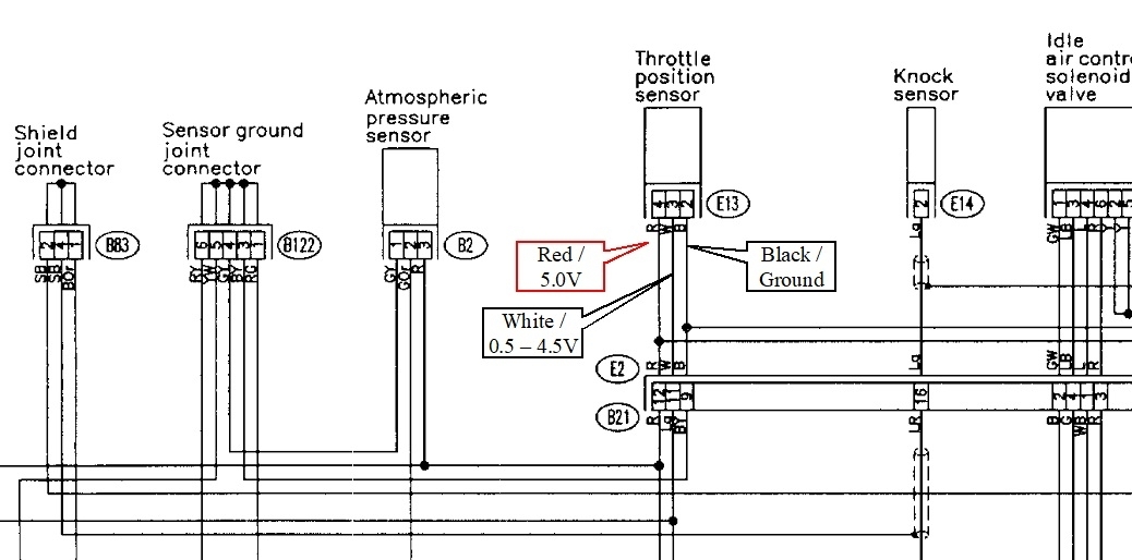
When you measure on the sensor's three wires, the ground wire should have 0.0 volts, the supply, or feed wire will have 5.0 volts, and the signal wire will have something in between, 0.5 to 4.5 volts, depending on throttle setting. This works on any model and you don't even have to know which wire is which.

To streamline this and potentially add a little confusion, especially when you DO know which wire is the signal wire, you only need to measure that one. If you find the signal voltage to be within that acceptable range, 0.5 to 4.5 volts, that can only happen when the ground and the 5.0-volt wires are working correctly. There's no need to test them so that can save a little time.

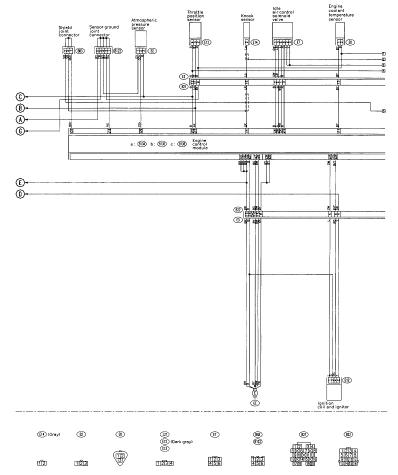
The diagram is one of four for Powertrain Management. The second one is just part of it blown up for easier viewing. I added the three callouts for the wires to the TPS. Let me know what you find on those for voltages. Will be back tomorrow to see how far you got.
Was this
answer
helpful?
Yes
No
Sunday, September 24th, 2023 AT 7:49 PM
Tiny
DAM LOUIS
  • MEMBER
  • 6 POSTS
Thanks, I will start with the TPS in the morning.
Was this
answer
helpful?
Yes
No
Sunday, September 24th, 2023 AT 8:19 PM
Tiny
DAM LOUIS
  • MEMBER
  • 6 POSTS
Good day,

sorry for the long delay in replying. I noticed that my battery was drained (looks like it had sat there inactive for too long).

I have sent it back to the seller either for charging or replacement, as it was still under warranty, but I have yet to receive it.

In the meanwhile I am cleaning and tightening every visible connection, and I shall get back to you as soon as I can start performing the recommended voltage tests.

Thanks for your patience.
Was this
answer
helpful?
Yes
No
Tuesday, September 26th, 2023 AT 11:24 PM
Tiny
DAM LOUIS
  • MEMBER
  • 6 POSTS
Good day again,

I received my battery with a voltage of about 13.11 volts dc. So, I decided to start carrying your recommendedd tests on the throttle position sensor as described.

I did not get the expected results so I decided to call it a day till I get better advice before I cause more harm.

I tested the voltages to the throttle position wires while disconnecting from the TPS with the Ignition in the on position.

The voltage on the 3 terminals were:
# 1 - 0 volts, continuity to ground.
# 2 - 4.8 v (middle terminal)
# 3 - 11.88 V

based on the information provided I decided to leave the battery disconnected pending further tests.

Best Regards,

Dama
Was this
answer
helpful?
Yes
No
Wednesday, September 27th, 2023 AT 10:44 AM
Tiny
CARADIODOC
  • MECHANIC
  • 33,752 POSTS
I thought those last two numbers were the clue we needed, but now, after looking at the diagrams, I'm really confused. First, there are references to the "electronic throttle body", implying this has "throttle-by-wire". Other places it shows an idle speed motor which is used when you have a throttle cable. Lets start by clearing me up on whether you have a throttle cable or not.

If you do, every vehicle I've ever seen, except for a few early ones from the early '80s, uses 5.0 volts to power their sensors. The 11.88 volts you found would not fly and would cause all kinds of fault codes. That would point to a 12-volt wire being shorted to the sensor feed wire. For that, look for a wire harness that is crushed between something, or white or bluish-green corrosion between two or more adjacent terminals in a connector. Less common would be a terminal that got bent over in a connector and is touching another terminal.

The other problem is the 4.8 volts you found on the signal terminal. All my training says there would have to be a break inside the sensor. The only other cause would be a break in the ground circuit, but that is okay as shown with the 0.0 volts you found on it.

At this point I have to stop and apologize; after rereading my last reply, I didn't fully explain that all voltage readings in sensor circuits are only valid when everything is connected and plugged in. If you measure the throttle position sensor's signal voltage while it is unplugged, you WILL get 0.0 or 5.0 volts, thanks to the pull-down or pull-up resistor. It's doing its job by forcing the signal voltage to go to a defective state so it can be detected by the computer. That could explain the 4.8 volts you found. That reading must be taken by back-probing alongside the wire while the sensor is plugged in. A stretched-out paper clip works well to poke through the rubber weather seal around the wire and touch the back of the terminal.

To get back to my original confusion, if you have a throttle cable, see what you get for signal voltage as you run the throttle from closed to wide-open. You can't do that if you have an electronic throttle. Nothing on the diagrams indicate whether that 11.88 volts is correct or too high. If it is correct, this would have to be an electronic throttle system, but the 4.8 volts on the signal wire still seems too high.

The other fault codes are of no help. They're pointing to conflicting causes which is what led me to originally expect to find a connector unplugged or a wire harness crushed or damaged. Codes 743 and 748 refer to the transmission, so we're in a completely different system. Codes 1510 and 1512 refer to two different parts of the idle speed solenoid.

Double-check the wiring harness and connectors. If you don't find anything there, I'll post the diagnostic chart for the throttle position sensor code P0123. The best approach is still to pick just one circuit / one fault code, and start with that. The chart will have you check wires for shorts and continuity. Once we find the cause of that code, it's typical that we'll find the cause of all of them.
Was this
answer
helpful?
Yes
No
+1
Thursday, September 28th, 2023 AT 10:16 PM

Please login or register to post a reply.

Sponsored links