Due to smog problems (could not pass) decided to:
1. Decarb engine (used BG44K)
2. Removed Intake Manifold and cleaned all egr ports.
3. Removed Throttle Body and cleaned all carbon.
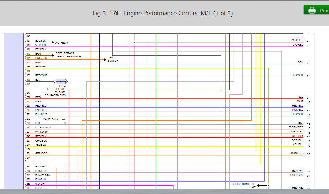
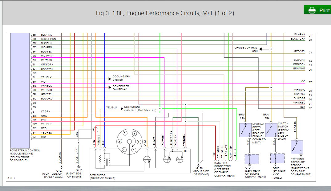
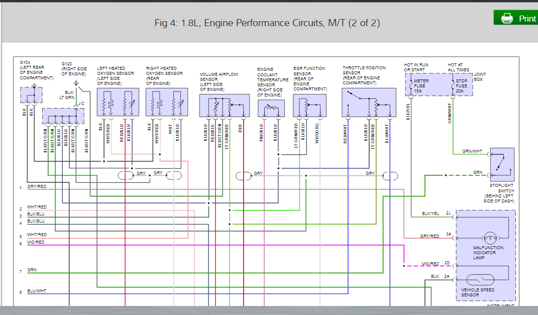
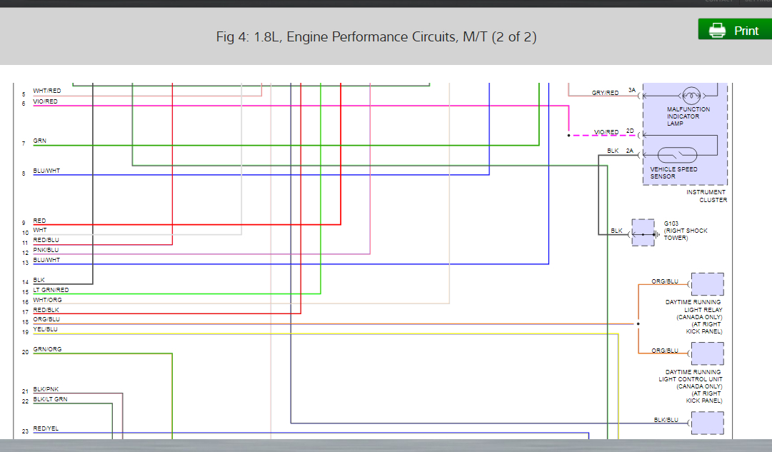
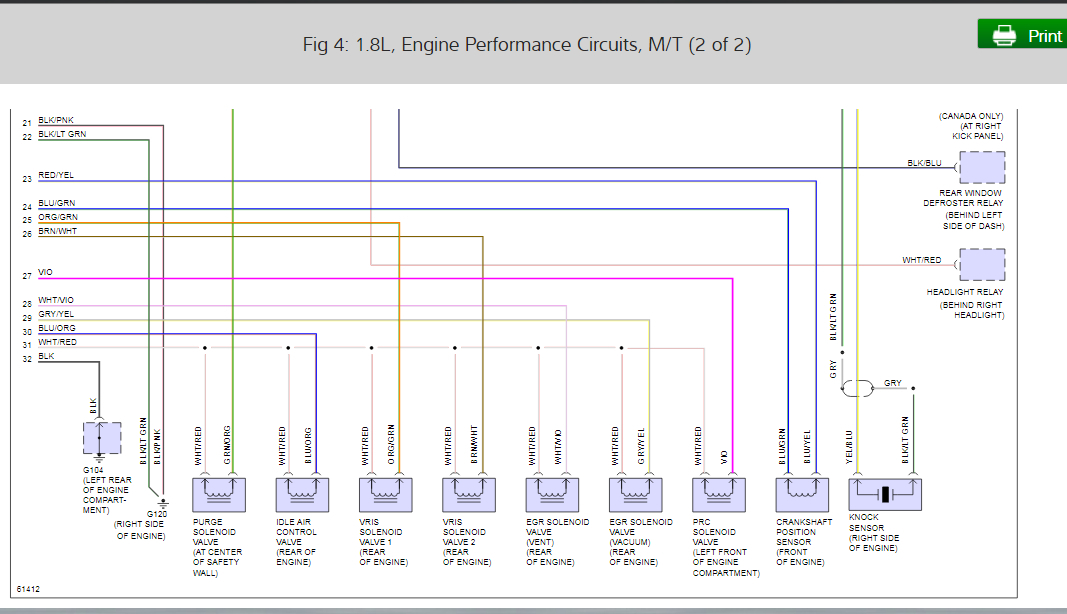
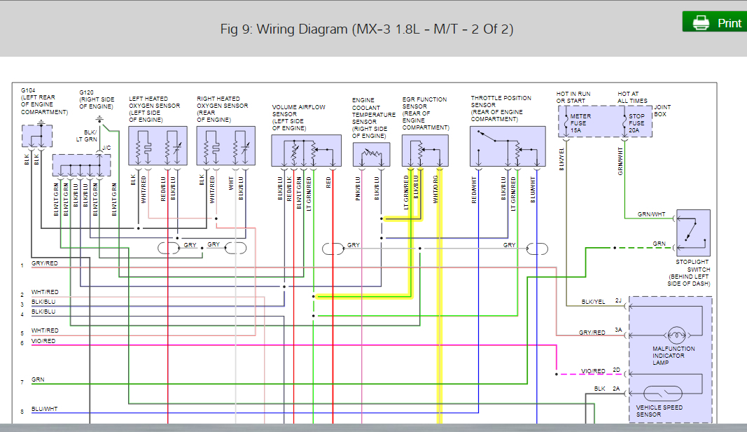
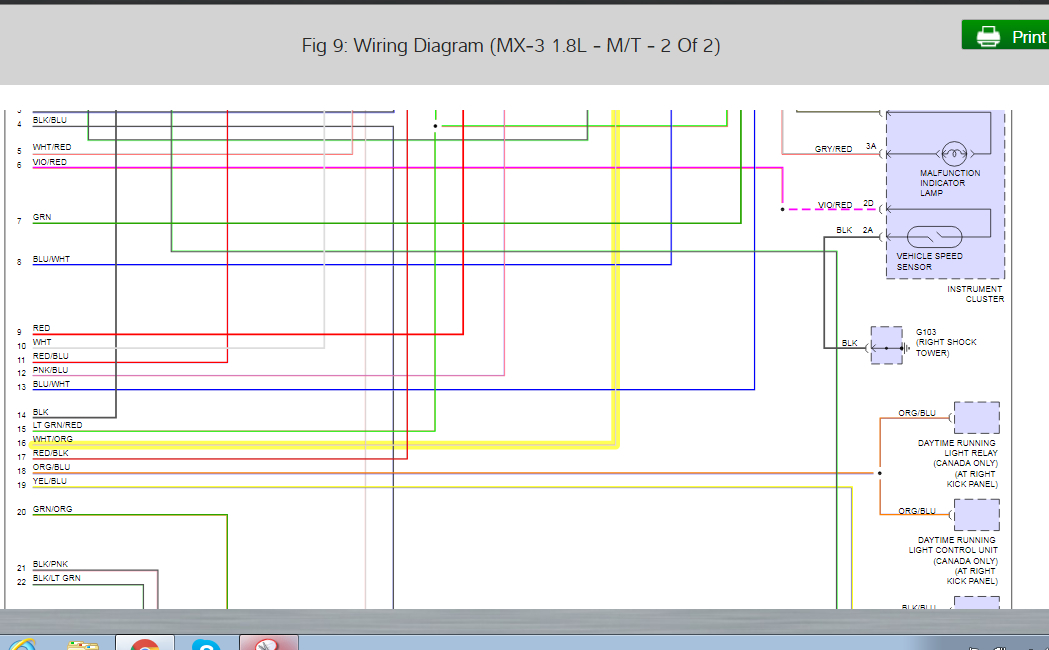
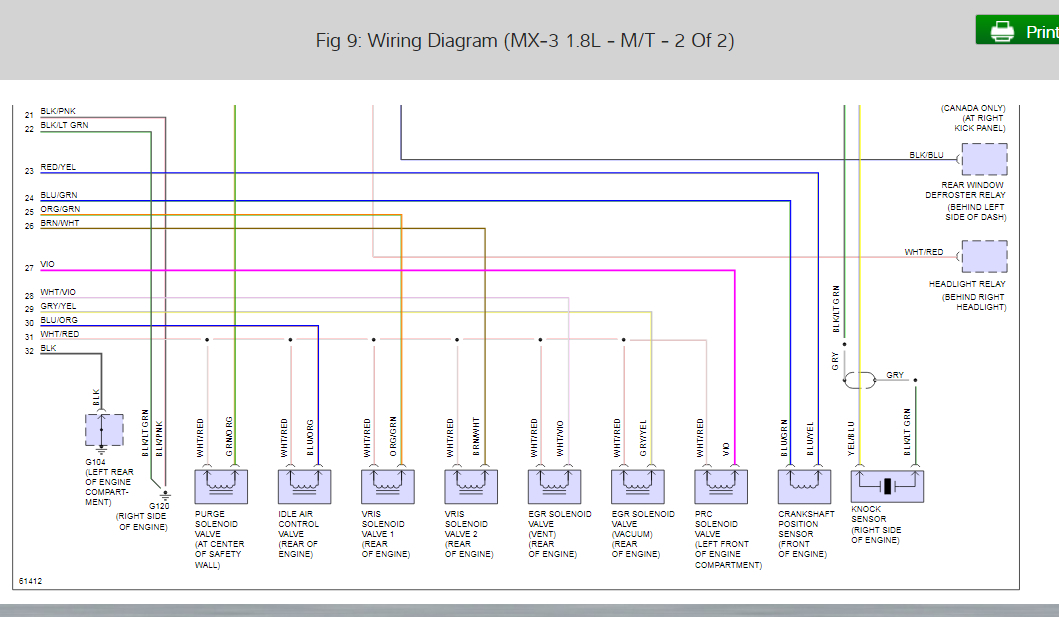
4. Changed EGR Valve: This is where the problems began. First of all the original was hard wired to the position sensor and vehicle harness. The EGR Valve has a removable position sensor connector. The original wires were cut to make a harness for making of a new harness that matched (??) the original three wire connection. The car runs great up to a point. At approximately 2800-3500 RPM I get a check engine light (2) The first OBD1 Code is 16 and the second 46. After the CEL comes on temporarily, I have a misfire.
5. At this point I am convinced that I did something wrong with the new harness and the presumption that the architecture of the Color Coding would be correct.
6. The problem now is the people that make the EGR Valve (intermodal) and the retail seller (SMP) cannot tell me which pins on the Sensor do what. They stated that this particular part is an OEM part. I can live with that but the manufacturer and the retailer should have some sense of how the EGR operates.
7. I am lost at this point and have high hopes someone has a guiding compass so I can resolve the issues.
8. Thanks in advance.
1. Decarb engine (used BG44K)
2. Removed Intake Manifold and cleaned all egr ports.
3. Removed Throttle Body and cleaned all carbon.
4. Changed EGR Valve: This is where the problems began. First of all the original was hard wired to the position sensor and vehicle harness. The EGR Valve has a removable position sensor connector. The original wires were cut to make a harness for making of a new harness that matched (??) the original three wire connection. The car runs great up to a point. At approximately 2800-3500 RPM I get a check engine light (2) The first OBD1 Code is 16 and the second 46. After the CEL comes on temporarily, I have a misfire.
5. At this point I am convinced that I did something wrong with the new harness and the presumption that the architecture of the Color Coding would be correct.
6. The problem now is the people that make the EGR Valve (intermodal) and the retail seller (SMP) cannot tell me which pins on the Sensor do what. They stated that this particular part is an OEM part. I can live with that but the manufacturer and the retailer should have some sense of how the EGR operates.
7. I am lost at this point and have high hopes someone has a guiding compass so I can resolve the issues.
8. Thanks in advance.
Apr 25, 2019 at 4:29 PM