Good morning,
The 160 code is related to the O2 sensor but more to wiring than the sensor.
The 401 is for the EGR. I would make sure the passages are clear of any debris. That is the most common failure for this code.
Roy
Circuit Description
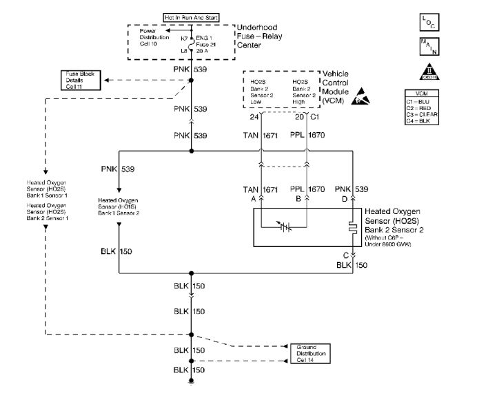
The heated oxygen sensor (HO2S) is a sensor designed to create a voltage relative to the oxygen content in the engine exhaust stream. The control module supplies the HO2S with signal high and low circuits. Ignition voltage and ground are supplied to the HO2S heater by independent circuits. The oxygen content of the exhaust indicates when the engine is operating lean or rich. When the HO2S detects that the engine is operating rich, the signal voltage is high, and decreases the signal voltage as the engine runs leaner. This oscillation above and below the bias voltage, sometimes referred to as activity or switching, can be monitored with the HO2S signal voltage.
The HO2S contains a heater that is necessary in order to quickly warm the sensor to operating temperature. The heater also maintains the operating temperature during extended idle conditions. The HO2S needs to be at a high temperature in order to produce a voltage. When the HO2S reaches operating temperature, the control module monitors the HO2S bias, or reference, voltage. It also monitors the HO2S signal voltage for Closed Loop fuel control. During normal Closed Loop fuel control operation, the control module will add fuel, or enrich the mixture, when the HO2S detects a lean exhaust content. The control module will subtract fuel, or "lean-out" the mixture, when the HO2S detects a rich exhaust condition.
Certain vehicle models utilize an oxygen sensor behind the catalytic converter in order to monitor catalyst efficiency.
This diagnostic trouble code (DTC) determines if the HO2S is functioning properly. It checks for an adequate number of HO2S voltage transitions above and below the bias range of 300-600 mV. This DTC sets when the vehicle control module (VCM) fails to detect a minimum number of voltage transitions above and below the bias range during the test period. Possible causes of this DTC are:
- An open or a short to voltage on either the HO2S signal or HO2S low circuits.
- A malfunctioning HO2S.
- A problem in the HO2S heater or its circuit.
- A faulty HO2S ground.
This DTC determines if the HO2S is functioning properly by checking for an adequate number of HO2S voltage transitions above and below the bias range of 300-600 mV. This DTC sets when the VCM fails to detect a minimum number of voltage transitions above and below the bias range during the test period. Possible causes of this DTC are listed below.
- An open circuit or a short to voltage on either the HO2S signal or HO2S low circuits.
- A malfunctioning HO2S.
- A problem in the HO2S heater or its circuit.
- A poor HO2S ground.
Conditions for Running the DTC
- No active TP sensor DTCs.
- No active EVAP sensor DTCs.
- No active IAT sensor DTCs.
- No active MAP sensor DTCs.
- No active ECT sensor DTCs.
- No active MAF sensor DTCs.
- No active misfire DTCs.
- No intrusive tests (i.e., EGR or Catalyst) in progress.
- No device control active.
- The system voltage is more than 9 volts.
- The engine run time is more than 120 seconds.
- DFCO not active.
- The ECT is 80°C (176° F) or more.
- The MAF is 15 g/s or more.
- DTC P0155 not active.
- The system is in closed loop.
Conditions for Setting the DTC
The O2 sensor voltage remains between 399-473 mV for more than 100 seconds.
Action Taken When the DTC Sets
- The control module illuminates the malfunction indicator lamp (MIL) if a failure is detected during 2 consecutive key cycles.
- The control module sets the DTC and records the operating conditions at the time the diagnostic failed. The failure information is stored in the scan tool Freeze Frame/Failure Records.
Conditions for Clearing the MIL or DTC
- The control module turns OFF the MIL after 3 consecutive drive trips when the test has run and passed.
- A history DTC will clear if no fault conditions have been detected for 40 warm-up cycles. A warm-up cycle occurs when the coolant temperature has risen 22°C (40°F) from the startup coolant temperature and the engine coolant reaches a temperature that is more than 70°C (158°F) during the same ignition cycle.
- Use a scan tool in order to clear the DTCs.
Diagnostic Aids
Important: Never solder the HO2S wires.
Check for the following conditions:
Check for exhaust system leaks upstream of the suspect HO2S. The leak may be very small and typically be within 30.5 cm (12 in.) of the suspect HO2S.
A malfunctioning HO2S heater or heater circuit
With the ignition ON and the engine OFF, the HO2S voltage displayed on a scan tool should gradually drop to below 0.150 volt, indicating that the heater works properly. If not, disconnect the HO2S and connect a test lamp between the terminals C and D. If the test lamp does not light, repair the open in the HO2S ground circuit or the HO2S ignition positive voltage circuit. If the test lamp lights, replace the HO2S.
The Intermittent Test
Use a scan tool in order to monitor this HO2S signal voltage. Move the related connectors and the wiring harness with a warm engine running at part throttle in Closed Loop. If the failure is induced, the HO2S signal voltage reading changes from its normal fluctuating voltage (above 600 mV and below 300 mV) to a fixed value around 450 mV. This may help to isolate the location of the malfunction.
An intermittent may be caused by any of the following conditions:
- A poor connection.
- Rubbed through wire insulation.
- A broken wire inside the insulation.
Thoroughly check any circuitry that is suspected of causing the intermittent complaint.
Test Description
The numbers below refer to the step numbers on the diagnostic table.
2. This step checks for proper sensor activity. When in Closed Loop fuel control the HO2S voltage should rapidly swing above and below the bias voltage.
4. This step checks the VCM and the HIGH and LOW circuits between the VCM and the HO2S connector for proper operation.
7. This step checks for proper HO2S heater circuit operation up to the HO2S connector.
8. This step checks for proper circuit resistance between the HO2S LOW circuit and VCM ground.
13. This step checks for proper circuit resistance between the HO2S LOW circuit and VCM ground with a COLD sensor. A loose HO2S or poor tread to exhaust electrical contact will cause higher resistance when the HO2S is cold. Although 500 ohms is allowed, typical resistance should be less than 50 ohms.
401
Circuit Description
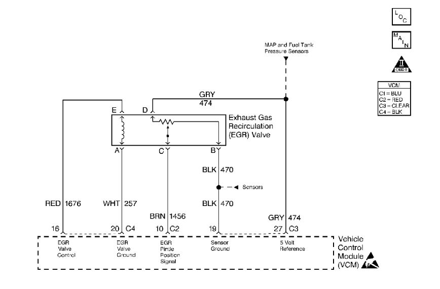
An exhaust gas recirculation (EGR) system is used in order to lower oxides of nitrogen (NOx) emission levels caused by high combustion temperatures. The EGR accomplishes this by feeding small amounts of exhaust gases back into the combustion chamber. When the air/fuel mixture is diluted with the exhaust gases, combustion temperatures are reduced.
A linear EGR valve is used on this system. The linear EGR valve is designed in order to accurately supply exhaust gases to the engine without the use of intake manifold vacuum. The valve controls exhaust flow going into the intake manifold from the exhaust manifold through an orifice with a control module controlled pintle valve. The control module commands the EGR by applying a 12 volt duty cycle to the EGR valve. This can be monitored on a scan tool as desired EGR position.
The control module can monitor the pintle position with the EGR pintle position signal. This sensor uses a variable resistor with a 5 volt reference, a signal circuit, and a ground. The signal circuit monitors changes in voltage on the variable resistor as the pintle moves.
The VCM tests the EGR system during deceleration by momentarily commanding the EGR valve open. The pressure in the intake manifold increases when the EGR valve is open. The VCM monitors the Manifold Absolute Pressure (MAP) sensor signal during the EGR system diagnostic in order to determine the amount of EGR flow. The MAP sensor will detect an increase in manifold pressure as the EGR is cycled ON. If the amount of manifold pressure observed is less than expected by the VCM, a DTC P0401 will be set.
Conditions for Running the DTC
- No active TP sensor DTCs.
- No active MAP sensor DTCs.
- No active VS sensor DTCs.
- No active IAT sensor DTCs.
- No active ECT sensor DTCs.
- No active IAC sensor DTCs.
- No active misfire DTCs.
- No active EGR pintle position DTCs.
- The ECT is more than 70°C (158°F).
- The BARO is more than 70 kPa.
- The vehicle speed is more than 27 mph (43 km/h).
- The change in IAC is less than 8 counts.
- The AC clutch status is unchanged.
- The transmission status is unchanged.
- The throttle position is less than 1 percent.
- The EGR position is less than 1 percent.
- The engine speed is between 1,00-1,900 RPM (manual transmission).
- The engine speed is between 800-1,600 RPM (automatic transmission).
- Any change in MAP is less than 0.5 kPa.
- DFCO not active (automatic transmission).
- No change in DFCO (manual transmission).
Conditions for Setting the DTC
During the EGR flow test, the change in MAP is less than a calibrated value for more than 2 seconds.
Action Taken When the DTC Sets
- The control module illuminates the malfunction indicator lamp (MIL) the first time the diagnostic runs and fails.
- The control module will set the DTC and records the operating conditions at the time the diagnostic fails. The control module stores the failure information in the scan tools Freeze Frame/Failure Records.
Conditions for Clearing the MIL or DTC
- The control module turns OFF the MIL after 3 consecutive drive trips when the test has run and passed.
- A history DTC will clear if no fault conditions have been detected for 40 warm-up cycles. A warm-up cycle occurs when the coolant temperature has risen 22°C (40°F) from the startup coolant temperature and the engine coolant reaches a temperature that is more than 70°C (158°F) during the same ignition cycle.
- Use a scan tool in order to clear the DTCs.
Diagnostic Aids
Notice: In order to prevent further damage if the EGR valve shows signs of excessive heat, check the exhaust system for blockage (possibly a plugged converter) using the procedure found on the restricted exhaust system check. If the exhaust system is restricted, repair the cause; one of which might be an injector which is open due to one of the following reasons:
- Stuck.
- Grounded driver circuit.
Check the oil for possible fuel contamination if a stuck open fuel injector is found.
Intermittent test --If connections and harness check OK, monitor a digital voltmeter connected between terminal EGR control circuit and ground while moving related connectors and wiring harness. If the failure is induced, the voltage reading will change.
An intermittent may be caused by any of the following conditions:
- A poor connection.
- Rubbed through wire insulation.
- A broken wire inside the insulation.
Thoroughly check any circuitry that is suspected of causing the intermittent complaint.
Test Description
The numbers below refer to the step numbers in the diagnostic table:
2. Correct any MAP sensor DTCs first.
3. This test ensures that the EGR valve is allowing EGR flow and the VCM is capable of controlling the EGR valve.
7. Clearing the DTCs is a very important step in this diagnostic procedure. The clearing function allows the EGR valve to relearn a new minimum pintle position, as the old position was inaccurate due to the malfunction that caused this DTC.
Images (Click to enlarge)
Jun 10, 2019 at 4:15 AM