Will a bad ECM cause instrument cluster to stop working and completely drain the battery?

Tiny
ALTASNOWMAN
  • MEMBER
  • 2002 DODGE TRUCK
  • 4.7L
  • V8
  • 2WD
  • AUTOMATIC
  • 13,000 MILES
Just wondering if the ECM is going will it cause instrument cluster to quit and completely drain the battery.
Thursday, November 17th, 2022 AT 7:41 AM

11 Replies

Tiny
JACOBANDNICKOLAS
  • MECHANIC
  • 108,300 POSTS
Hi,

No, I don't feel that would happen. I attached the wiring schematic below for the entire instrument cluster. Power is provided to the cluster and then primarily, switches control how it functions.

What is happening? Let me know in detail what you have experienced.

Also, I need to know if this is a Dakota or full-size truck. Both had the 4.7L as an option. The wiring schematic I attached is for a full size 1500 2wd.

Let me know.

Joe

See pics. I had to cut one page in two to make it readable. I did overlap them so you can follow from one to the next.
Was this
answer
helpful?
Yes
No
Thursday, November 17th, 2022 AT 5:09 PM
Tiny
ALTASNOWMAN
  • MEMBER
  • 39 POSTS
Hi, pulled fuse and gauges came back but now I have another problem. It is a full-size truck, and the check engine light is on now but not charging. Changed the ECM as I thought it was there but check engine light is on. Checked for codes but nothing shows. Truck will run until it kills battery. Now I do not know what is wrong.
Was this
answer
helpful?
Yes
No
Friday, November 18th, 2022 AT 2:53 PM
Tiny
JACOBANDNICKOLAS
  • MECHANIC
  • 108,300 POSTS
Hi,

If it isn't charging, in most cases it is either the alternator or the ECM. Is the ECM new that you installed? Have you had the alternator bench tested?

Let me know. Also, if the ECM was used, it may be the issue. Also, there is a fusible link between the alternator and battery that may have failed. It will be a black wire with a gray tracer. Locate it at the alternator and confirm it has B+ voltage. If it doesn't, the alternator will not work.

If the fusible link is good and you are certain the ECM is good, then I would recommend removing the alternator and having it bench-tested at a parts store. They will do it free of charge.

I attached the wiring schematic below for the charging system, so you have it as a reference. It was one page long, but I had to cut it in half to make it readable.

Let me know what you find.

Take care,

Joe

See pics below.
Was this
answer
helpful?
Yes
No
+1
Friday, November 18th, 2022 AT 8:07 PM
Tiny
ALTASNOWMAN
  • MEMBER
  • 39 POSTS
Just had alternator tested and it is ok. The ecm was checked at dealer and it is ok. Does the ignition key need to be on to test the fuseable link?
Was this
answer
helpful?
Yes
No
Sunday, November 20th, 2022 AT 12:59 PM
Tiny
ALTASNOWMAN
  • MEMBER
  • 39 POSTS
Oh, I think I changed the wrong module. The ECM is the one on the firewall? If it is, then I changed out the wrong mod and will have to get the one that I should of changed out re programmed as I plugged in the replacement, but truck will only run for a few seconds. Am I correct that the ECM is the one that takes three separate plugs?
Was this
answer
helpful?
Yes
No
Sunday, November 20th, 2022 AT 2:51 PM
Tiny
JACOBANDNICKOLAS
  • MECHANIC
  • 108,300 POSTS
Hi,

The fusible link in this case should have power at all times and doesn't require the key to be on.

The PCM/ECM is on the right side of the firewall, and it will have at least 3 connectors. Looking at the schematic I attached above, pic 2 shows the PCM. Notice the pins are numbered starting with the letter C. The C identifies the connector number the wire goes to.

Let me know if that helps.

Take care,

Joe
Was this
answer
helpful?
Yes
No
-1
Sunday, November 20th, 2022 AT 8:39 PM
Tiny
ALTASNOWMAN
  • MEMBER
  • 39 POSTS
Hi Joe, I think you forgot to attach the schematic, but regardless I am going to get the mod flashed this morning and will update when I get back and fingers crossed this works as I am running out of money, luck and patience.
Was this
answer
helpful?
Yes
No
Monday, November 21st, 2022 AT 7:07 AM
Tiny
JACOBANDNICKOLAS
  • MECHANIC
  • 108,300 POSTS
Hi,

I hope that takes care of things. Let me know. Also, the schematic is above in an earlier post, but I reattached it below.

Let me know how things turn out for you.

Take care,

Joe

See pic below.
Was this
answer
helpful?
Yes
No
Monday, November 21st, 2022 AT 6:35 PM
Tiny
ALTASNOWMAN
  • MEMBER
  • 39 POSTS
Well, my ECU has indeed gone south and the fact that everything that I checked was good. Voltage regulator in ECU is bad. I have been told that rather than pay (through the nose) for flashing the replacement ECUI should install an external voltage regulator. I need to know how to do this as it is something new to me and have no idea how to do this.
Was this
answer
helpful?
Yes
No
Monday, November 21st, 2022 AT 9:40 PM
Tiny
JACOBANDNICKOLAS
  • MECHANIC
  • 108,300 POSTS
Hi,

I'm not sure how you would do that and don't feel it would work with the system. Have you checked online for a remanufactured ECM? There are many sites that provide plug and play rebuilt ones that won't require programming.

In the past, I've used them and have had no problem to date.

It's a thought. I believe my last one was 119.00.

Let me know.

Joe
Was this
answer
helpful?
Yes
No
+1
Tuesday, November 22nd, 2022 AT 5:53 PM
Tiny
CARADIODOC
  • MECHANIC
  • 33,752 POSTS
Hi guys. There's one more thing to consider. The external voltage regulator from a 1970 through late '80s Chrysler will run this alternator just fine, but the resulting lack of field current flow through the Engine Computer's voltage regulator circuit will be detected, and the diagnostic fault code, "field circuit not switching properly" will set. Since that normally refers to a failure-to-charge and therefore low system voltage, that can adversely affect injector response and ignition spark strength. Those two things could adversely affect emissions, therefore, that fault code turns on the Check Engine light.

Once the Check Engine light turns on, some of the hundreds of tests the computer continually runs will be suspended. That is when a second, or third, totally unrelated problem could develop, along with a variety of symptoms, but not be detected by the computer. No one, especially the mechanics, would find any new fault codes or have that information to direct them to the circuit or system that needs further diagnosis. You would have to fix the first problem the proper way, with a replacement computer, erase that fault code, then drive the vehicle until the newer problems are detected.

This is where you'll hear stories about someone getting their vehicle repaired, they leave the parking lot, and within a fraction of a minute to a few miles the Check Engine light turns right back on again. The owner incorrectly assumes the vehicle wasn't repaired correctly or wasn't diagnosed correctly. The mechanic is frustrated because he had no way of knowing once the first repair was completed, and the suspended tests resume, that the newer problem will now be detected, and the light may turn on again. This is more likely to happen when a lot of time passes, as in many months, before the first problem is addressed. That gives all that time for the new problem to develop.

In addition, even if a new, second or third problem develops, you would never know because the Check Engine light is already on, so it gets ignored. That can result in a fairly simple or inexpensive problem turning into a very expensive repair.

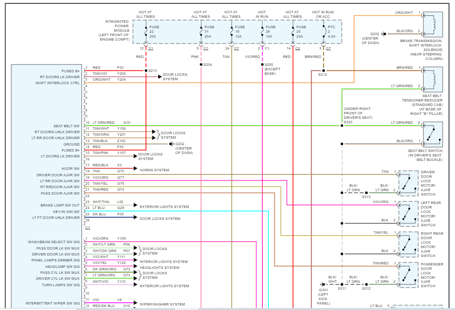
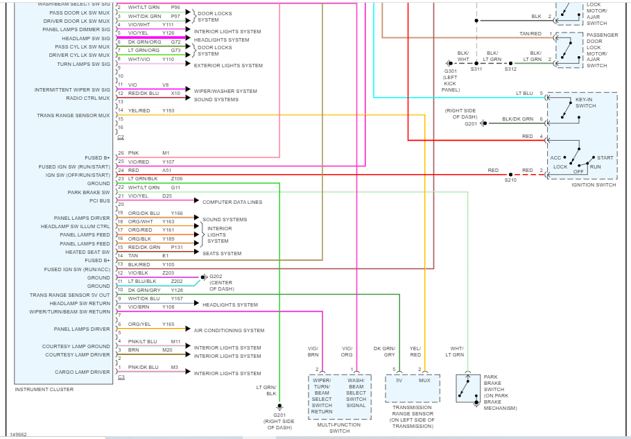
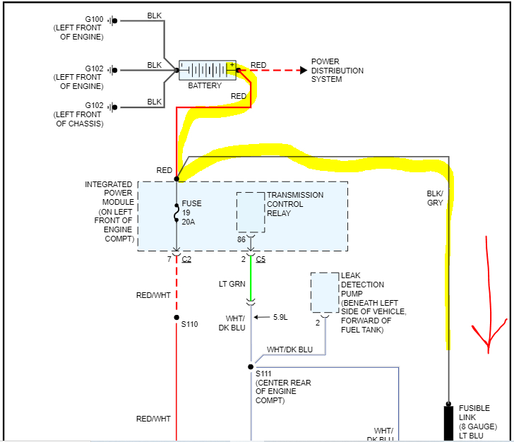
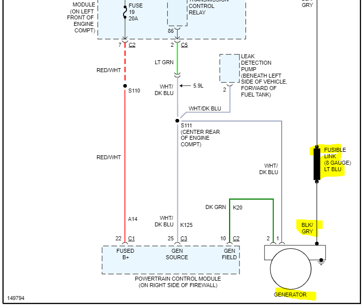
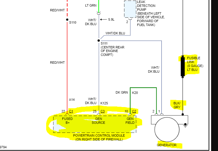
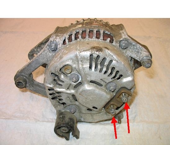
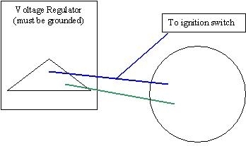
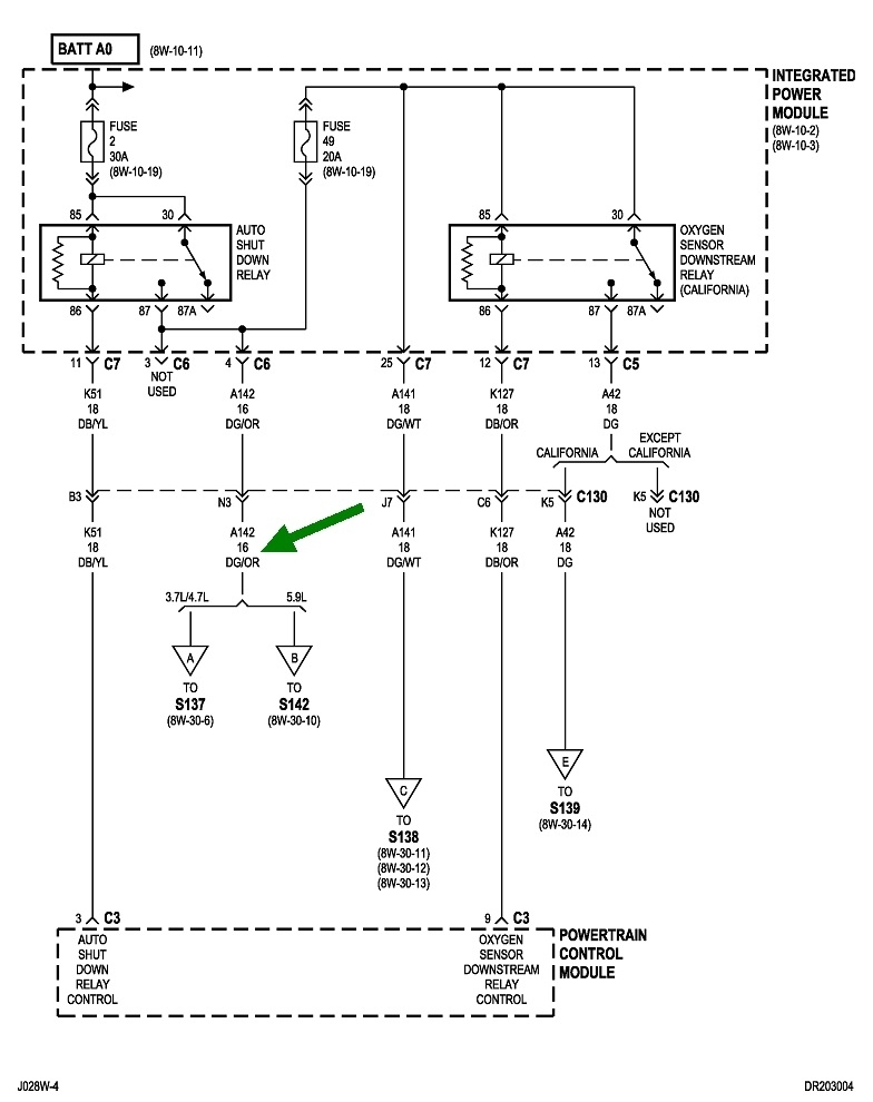
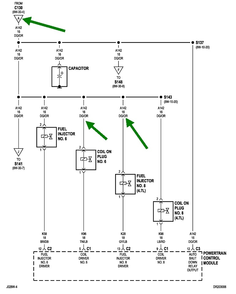
If you want to pursue this for a temporary fix, use the simple diagram below. You will likely have a little silver Nippendenso alternator as shown in the first photo. There's two small terminals on the rear. They're interchangeable. My sad drawing shows the three-terminal plug that has just two wires in it, a dark blue one and a dark green one, for the regulator. Those two wires go to the two terminals on the back of the alternator. Then, the dark blue wire gets tied to anything under the hood that gets 12 volts switched on. On the older models, everything dark blue under the hood got 12 volts switched onto it through the ignition switch when it was turned to "run". On newer models like your truck, the field current is switched on through the automatic shutdown, (ASD) relay. You can get that 12 volts from the positive terminal on one of the ignition coil, or the 12-volt feed wire at any of the injectors. The third diagram shows the ASD relay switching 12 volts onto the dark green / orange wire at all of those places. That's the most often used color now instead of dark blue. The fourth diagram shows the same wire / circuit at two of the ignition coils and two of the injectors. All six of the others are exactly the same, so you can use that wire at any of them.

I don't consider this a proper repair or anything other than a temporary fix, but it can get you back on the road again. These regulators were very inexpensive, as in usually under $20.00. They also have a third terminal that must be used. That is the metal housing bolted to the body sheet metal for the ground. Be sure paint and rust don't interfere with that connection.

(In the second drawing, top right, where it says, "to ignition switch", for your truck it should say, "to ASD relay circuit", or "to dark green / orange wire).
Was this
answer
helpful?
Yes
No
Tuesday, November 22nd, 2022 AT 7:23 PM

Please login or register to post a reply.

Sponsored links