1993 Dodge Ram Charging problem

Tiny
RFOX123
  • MEMBER
  • 1993 DODGE RAM
  • 6 CYL
  • 2WD
  • MANUAL
  • 200,000 MILES
I have replaced the PCM with the voltage regulator in it. I have also replaced the alternator with no voltage regulator. The vehiicle will not charge the battery. I have a 1993 Dodge Ram 250 pickup and cannot figure out this problem. Please help me.
Thursday, July 22nd, 2010 AT 6:04 PM

12 Replies

Tiny
CARADIODOC
  • MECHANIC
  • 33,738 POSTS
Hi rfox123. Welcome to the forum. Start by measuring the voltages on the two small wires on the back of the alternator. They have to be measured while the engine is running, not with just the ignition switch turned on.

One will have full battery voltage. The key is the other one. It should have less than battery voltage but not 0 volts. Let me know what you find.

Caradiodoc
Was this
answer
helpful?
Yes
No
Thursday, July 22nd, 2010 AT 6:22 PM
Tiny
RFOX123
  • MEMBER
  • 6 POSTS
There is 0 voltage on both wires. Does it matter if it is a diesel?
Was this
answer
helpful?
Yes
No
Thursday, July 22nd, 2010 AT 6:39 PM
Tiny
RFOX123
  • MEMBER
  • 6 POSTS
Thanks for not helping a brethren in your field. I am a retired mechanic and needed some help with the electrical work. Stick your webpage up your butt. The $25 I spent was worthless to me. No help was offered except to check a few wires. No response with my reply. THANKS AGAIN.
Was this
answer
helpful?
Yes
No
-1
Thursday, July 22nd, 2010 AT 8:07 PM
Tiny
CARADIODOC
  • MECHANIC
  • 33,738 POSTS
What in the world did I do to deserve that kind of attitude. I DO like to eat and sleep every few days. In this case, I just had a three week old hard drive crash a few minutes after I posted my reply. This is the seventh laptop crash in four computers since the first of the year. I can't keep spending hundreds of dollars every month to help ungrateful people. I hooked up a ten-year-old tank that has never failed me, then headed right back to the computer to see if you replied. Do you still want help? If so, I promise I won't leave to go to the bathroom or search for a service manual on your behalf.

You didn't give any preliminary test information. That's why I asked you to measure the two voltages as a starting point. I don't know what you expected, but this is a real simple circuit that can be broken down into two parts.

Now, thank you for providing the readings. Had you taken those first, you would have known neither the Engine Computer nor the alternator would solve the problem. Do I dare ask you to confirm the engine was running when you took the readings? At the risk of getting chewed out further, you WILL have 0 volts on those wires with the engine stopped.

Yes, it does make a difference if it's a diesel; not in the circuit, but in the symptoms. The alternator field gets it voltage from the automatic shutdown relay, but that relay also feeds the injectors and coil(s) on gas engines so they can be used for diagnosis too. A dead ASD circuit would result in a no-start condition. For the diesel engine, I don't see any reference to anything else getting voltage from the ASD relay, so that would be the best guess at this point. Swap the ASD relay with a different similar one to see if you get battery voltage to the field terminals with the engine running. If you still don't have voltage, we have to determine if that relay is turning on. Since we don't have working ignition coils to prove the ASD relay is turning on, you can pop the cover off the relay and watch the movable contact, or poke a wire into the terminal and use it as a test point. I'll describe which terminal if you want to pursue that approach.

If a known good relay is turning on, that leaves only the wire from the relay to the alternator. There is one 6-pin connector in the middle of that wire. It is on the right side of the intake manifold. The 12 volt feed wire from that connector to the alternator is dark blue. Up to the connector, the wire is dark green with an orange tracer.

You can also check for voltage at all times on one pin of the ASD relay. There is a fusible link wire in that circuit but it also feeds the ignition switch and Engine Computer, so chances are that circuit is ok.

Caradiodoc
Was this
answer
helpful?
Yes
No
+3
Thursday, July 22nd, 2010 AT 10:08 PM
Tiny
RFOX123
  • MEMBER
  • 6 POSTS
Sorry for the attitude, I am a retired auto mechanic and now work as a maintenance mechanic in a power plant, working outdoors in 100 plus temperatures what with the weather, coal burning and such. I have talked to supposedly certified ASE mechanics and master mechanics and no-one can help me solve this problem. I am color blind so I can't tell the color of the wires, etc. Nobody seems to understand that this is a 1993 Dodge Ram 250 with a rare manual 5 speed transmission. They keep giving me schematics for an automatic transmission. Also, this is a diesel truck, not gasoline. I know enough about changing trannies, engines, suspension, steering, etc but never got into the electric parts, due to the color blindness. Thanks for trying to help me anyway. Again, sorry for the attitude. Just tired and disgusted. Don't do computers either. Downfall of mankind. That is why I have a wife. So. Go eat and sleep. I am going to do the same. Thanks again.
Was this
answer
helpful?
Yes
No
Thursday, July 22nd, 2010 AT 11:38 PM
Tiny
CARADIODOC
  • MECHANIC
  • 33,738 POSTS
When the book on frustration was written, my life was the feature story. Problem is, when I have a bad day, they last on average, six weeks, so I know the feeling. Thanks for understanding. Together, we'll figure out this problem.

When you get the chance, play with the ASD relay. I forgot that the relays aren't plugged into an under-hood fuse box. According to the drawings in the service manual, there are four relays on the left fender mounted individually. That makes accessing the wires a lot easier. The ASD relay is the second one from the front. The first one is listed as the fuel pump relay. That one might not be used on a diesel truck. The red wire, (one of the two fatter wires), should have battery voltage all the time and the dark green / orange wire, (the other fatter wire), should have battery voltage when the engine is running and the relay has turned on.

If the second wire doesn't have 12 volts while the engine is running, look at the two skinnier wires. Both must have 12 volts when the ignition switch is turned to "run", but one will go to 0 volts to turn the relay on when the engine is running. If that's confusing, just use a test light or cheap digital voltmeter to measure the voltages on all four wires, once with the ignition switch turned to "run" and again with the engine running. Holler back when you have those numbers. They will help us determine where to go next.

Caradiodoc
Was this
answer
helpful?
Yes
No
+3
Friday, July 23rd, 2010 AT 3:10 AM
Tiny
RFOX123
  • MEMBER
  • 6 POSTS
Thank you for understanding, engine running, fat red wire 12.65 volts, black, -0-, skinny single wire-0, two skinny wires together, -0-. Ignition switch on, red wire 12 volts, nothing on any of the other wires. Thanks for your help.
Was this
answer
helpful?
Yes
No
Friday, July 23rd, 2010 AT 8:08 AM
Tiny
CARADIODOC
  • MECHANIC
  • 33,738 POSTS
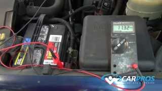
Dandy. It appears voltage is not getting to the ASD relay to turn it on. You can verify the rest of the circuit is working by using a stretched out paper clip or a piece of wire to jump between the two fatter wires in the relay. If you turn on the headlights or have an under-hood lamp, you should see them get brighter when the alternator starts charging.

The secret is the no voltage to either of the small wires to the relay. The one in question is dark blue with no stripe. The other one is also dark blue but has a stripe. Here's the kicker. That dark blue wire also feeds the two air heater relays. Do you hear them click when you turn on the ignition switch? And do you hear them click off? I think they click off at the same time the "Wait to Start" light turns off. If they are clicking, the ignition switch is ok and the problem has to be between a splice in that circuit and the ASD relay.

If those air heater relays aren't working, the problem is in that dark blue wire circuit between the ignition switch and the splice between the relays. Suspect the switch first, and the connection in the bulkhead connector next. The problem can not be in the wiring before the ignition switch because it also feeds the radio and turn signals. You would have noticed them not working.

The ignition switches did cause a lot of trouble, but not on that circuit. Typically it is the contact that feeds the power windows, radio, and high-current drawing heater fan circuit that causes the trouble.

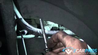
I think accessing that wire is easier at the ignition switch than at the bulkhead connector. If the air heater relays are clicking, skip this paragraph. If they are also dead, remove the covers on the steering column under the steering wheel. As I recall, there are four torx-head screws. Three hold the two halves together and one holds the bottom half to the column, then they snap apart. Due to the color issue, look at the size of the terminals in the back of the connector. There are seven terminals. Starting from one end, the first four are all large terminals. Starting from the other end, the first and third ones are much smaller. It's the larger one in between those two smaller ones you want, (the second from that end). There must be 12 volts there with the ignition switch turned to "run". If it is missing, double-check for voltage coming to the switch to prove to yourself it is there. That would be on the red wire which is the first large terminal on the other end of the plug with the four large terminals. If you jump between those two wires in the connector while the engine is running, lights should get brighter. That will be your proof the switch is defective or the terminals have overheated. If you see signs that the connector has melted or the first couple of inches of wire have become stiff, I'll describe how I replaced individual terminals without having to replace the entire harness. I'll skip that for now because the circuit you're in really doesn't have to handle that much current so I don't think that will be the problem.

If the air heater relays are working, the ignition switch and bulkhead connector have to be ok. The most likely suspect would be a corroded splice that has allowed one wire, (so far), to break loose from the rest. That splice is located inside the taped-up harness just under the rear edge of the hood, about 8 - 12" straight left of the wiper motor. It appears to be midway between the wiper motor and inner fender. Before you have tape flying in every direction, you might try flexing the harness in that area to see if the alternator starts working. If it does, you can have confidence you're in the right area. Either way, I don't like making a mess of harnesses by tearing them apart, but that might be what we have to do. You might have to find a helper if looking at the wire colors becomes a problem. There's another splice in that harness a few inches closer to the wiper motor. I can't tell how many wires there are in that splice or their color, but the splice you're after has five dark blue wires tied together. Check for voltage at that splice. If it is there, the problem is between that splice and the ASD relay. If it is missing, the problem is between that splice and the ignition switch.

Caradiodoc
Was this
answer
helpful?
Yes
No
+1
Friday, July 23rd, 2010 AT 3:24 PM
Tiny
RFOX123
  • MEMBER
  • 6 POSTS
Thank you again for all of your help. I finally just gave up and took it to the Dodge dealer. They agree that there is a broken wire or a splice loose. I no longer have the patience to deal with it. This is only the 2nd time in my life that anyone else has worked on my vehicles. I have always been able to do the work myself, but this was too much. I have been dealing with the problem for 2 weeks already and am getting tired of keeping the battery charger on the truck. If you are ever in Florida, you have several beers coming on me. Just email ahead of time and let me know. Again, thank you for all of your patience. You have a great sense of humor by the way. Just about like mine.
Was this
answer
helpful?
Yes
No
Friday, July 23rd, 2010 AT 5:19 PM
Tiny
CARADIODOC
  • MECHANIC
  • 33,738 POSTS
I'll take you up some day on a rrrroots beer. If you can, post the results of what they find. Always nice to add it to the memory banks.

Caradiodoc
Was this
answer
helpful?
Yes
No
Friday, July 23rd, 2010 AT 5:50 PM
Tiny
RFOX123
  • MEMBER
  • 6 POSTS
Cardiodoc,
The dealership changed a wire from the ignition, which I had already checked and there was voltage. Now they say the cranking sensor is bad and need to change it. However, several mechanic friends and I cannot see what the cranking sensor has to do with a charging problem. Is this possible. What does that have to do with it? Thanks again for all of your help.
Was this
answer
helpful?
Yes
No
Monday, July 26th, 2010 AT 8:56 AM
Tiny
CARADIODOC
  • MECHANIC
  • 33,738 POSTS
The crankshaft position sensor provides pulses to the Engine Computer to tell it when to fire the coils and injectors on gas engines. It also tells it to turn on the ASD relay when the engine is rotating. The coil, injectors, fuel pump or pump relay, and alternator field get their power from the ASD relay when it turns on. On your engine, the only thing getting power from the ASD relay is the alternator field, but the computer also uses the engine speed information to determine, in part, when to shift the transmission into overdrive. It also uses it to run the tach, so if your tach is working, the sensor is too.

Two thoughts come to mind. First of all, we had this narrowed down to a break in the wire from the ignition switch to the ASD relay. Now it appears there is a second problem. What's the chances of two unrelated problems causing the same symptom at the same time? My second concern is their comment about "changing a wire". I had a dozen cars with prepared "bugs" for my students to practice their troubleshooting skills. Part of the exercise was to tell me the most economical, legitimate fix. For a break in a wire, it was not acceptable to simply run a new wire. They needed to find exactly where the break was located so they could determine WHY it broke. If a harness fell down onto a hot exhaust part, or it was rubbing across a sharp metal bracket, how long would it be before the second wire did the same thing? In the case of a splice, such as appeared to be the case with your truck, how long before the second wire corrodes off and affects a different circuit? You will be diagnosing a different problem that would have been found the first time and corrected.

Caradiodoc
Was this
answer
helpful?
Yes
No
+1
Monday, July 26th, 2010 AT 1:46 PM

Please login or register to post a reply.

Sponsored links