Hi and thanks for using 2CarPros.
That is an interesting one. I am going to provide the directions for removing and replacing the head and injectors. See if there is anything you may have missed. All pictures correlate with these directions.
_________________________________________
Cylinder Head, Removing and Installing
Vehicle Engine, Cooling and Exhaust Engine Cylinder Head Assembly Service and Repair Procedures Cylinder Head, Removing and Installing
CYLINDER HEAD, REMOVING AND INSTALLING
Cylinder head, removing
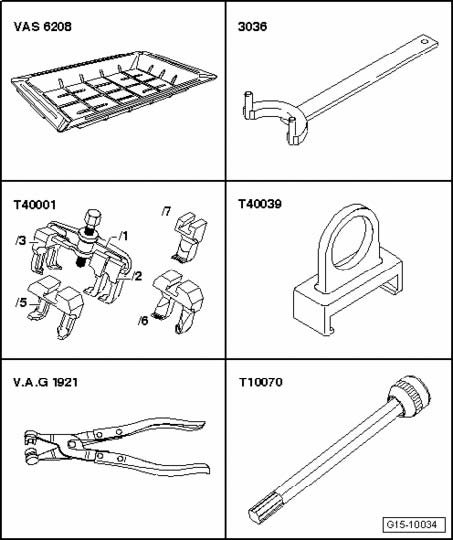
Special tools, testers and auxiliary items required
Picture 1
Drip tray for workshop crane VAS 6208
Counter-holder tool 3036
Puller T40001
Puller T40039
Hose clamp pliers V.A.G 1921
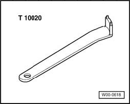
Special tools, testers and auxiliary items required
Pin wrench T10020
Picture 2
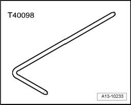
Drift T40098
Picture 3
Removing
Engine installed.
Note:
All cable ties which are opened or cut open when removing, must be replaced in the same position when installing.
If oil is dirty, perform an oil change:
When using sealant, observe the current descriptions.
- Note radio code (for vehicles equipped with coded anti-theft radio / radio navigation system), obtain if necessary.
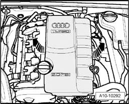
Picture 4
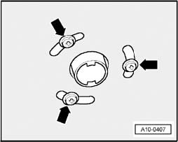
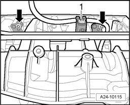
- Remove engine cover - arrows -.
CAUTION: Cover cap of expansion tank with rag and open carefully, as hot steam or hot coolant may escape when opening.
- Open cap of coolant expansion tank.
Picture 5
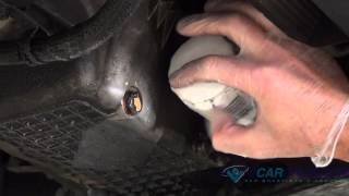
- For vehicles with auxiliary heater, remove bolts - arrows - for exhaust pipe of parking heater/auxiliary heater on sound insulation.
Picture 6
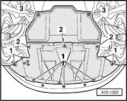
- Loosen quick-release fasteners - 1 - and - 2 - and remove front sound insulation.
- Drain engine coolant
- Remove toothed belt.
Picture 7
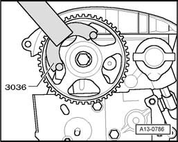
- Loosen bolt for camshaft sprocket using counter-holder 3036.
Picture 8
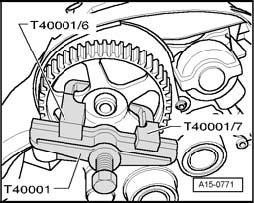
- Pull off camshaft sprocket using two-arm puller T40001 and claw T40001/6 and claw T40001/7.
Picture 9
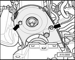
- Remove rear toothed belt housing from cylinder head - arrows -.
Picture 10
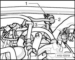
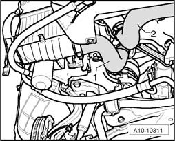
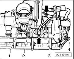
- Disconnect Ground (GND) cable - 1 -.
- Disconnect vacuum line to brake booster at bulkhead - 2 -.
- Disconnect EVAP hose - 3 -.
Picture 11
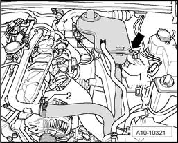
- Remove coolant hoses - 1 and 2 - and unfasten coolant expansion tank - arrow -
- Disconnect electrical connection at Engine Coolant Level (ECL) Warning Switch F66 at bottom of coolant expansion tank.
Picture 12
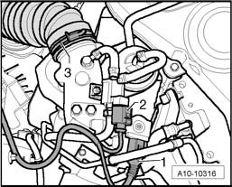
- Disconnect electrical connector from Charge Air Pressure Sensor G31 - 1 -.
- Remove left charge air hose - 2 -.
Picture 13
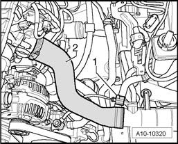
- Remove air duct hose - 1 - to turbocharger at bottom right.
- Remove air duct hose - 2 - to charge air cooler at lock carrier.
Picture 14
- Disconnect connector - 1 and 2 - and free up cable.
Picture 15
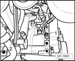
- Unfasten oil supply line for turbocharger at cylinder block - 1 -.
- Remove bolt - 2 - of support for turbocharger.
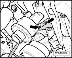
Picture 16
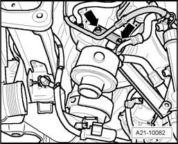
- Remove oil supply line for turbocharger - arrows -.
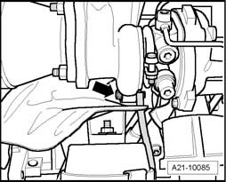
Picture 17
- Disconnect oil return line - arrows - from turbocharger.
Picture 18
- Loosen support bolt - 1 - for turbocharger by 2 turns.
- Remove intake manifold
- Remove catalytic converter
- Remove cylinder head cover
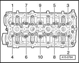
Picture 19
- Loosen cylinder head bolts, paying attention to sequence of cylinder head bolts.
Note: Verify that all hose and line connections between engine, transmission and body have been disconnected.
- Remove cylinder head.
Cylinder head, installing
Note:
Replace cylinder head bolts.
Always replace self-locking nuts, bolts which have been tightened to tightening torque as well as gaskets and O-rings.
Secure all hose connections using hose clamps appropriate for the model type.
Carefully remove residual sealant from cylinder head and cylinder block. Make sure that no long scrapes or scratches result.
Thoroughly remove all grinding and sanding residue.
Only unpack new cylinder head gasket immediately prior to installation.
Handle gasket carefully. Damages to the silicone layer and in areas of recesses may result in leaks.
There must be no oil or coolant in the blind holes for the cylinder head bolts in the cylinder block.
High-temperature lubricant
CAUTION: Only turn over the engine at the crankshaft in direction of engine rotation (clockwise).
Note: Turning over the engine is performed at the central bolt of the crankshaft.
Picture 20
- Bring marking on camshaft gear to alignment with marking on toothed belt guard. Recesses - arrows - now point to each other vertically.
- In case the crankshaft was turned in the meantime: Set piston of cylinder 1 to TDC and turn crankshaft back again slightly.
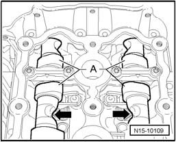
Picture 21
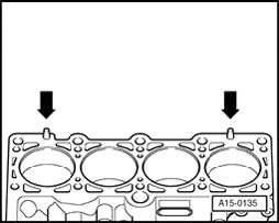
- Set cylinder head gasket in place.
Pay attention to centering pins in cylinder block - arrows -.
Observe installed position of cylinder head gasket, Marking: Replacement part number must be legible from intake side.
- Set cylinder head in place.
- Insert cylinder head bolts and tighten by hand.
Picture 22
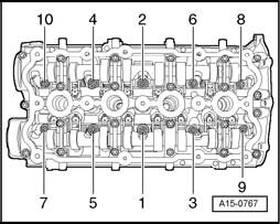
- Tighten cylinder head in sequence indicated, in two stages as follows:
- Tighten with torque wrench:
1. Step: 40 Nm
- Tighten using a solid wrench:
2. Step: 180° (1/2 turn) further (2 x 90° further is permissible)
Note: There is no requirement to retighten the cylinder head bolts after repairs.
- Install cylinder head cover.
- Install toothed belt.
- Install ribbed belt.
- Electrical connections and routing:
- Install the intake manifold
- Connect battery.
- Bleed fuel system.
- Check oil level.
- Fill with coolant.
Note:
Only reuse drained coolant if cylinder head or engine block was not replaced.
Dirty coolant must not be re-used.
- Install lock carrier with attachments.
Picture 23
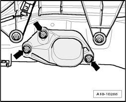
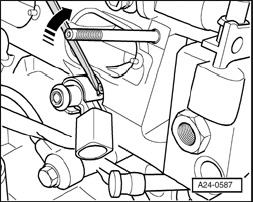
- Place torque support stop onto rubber buffer for torque support under its own weight and tighten nuts - arrows -.
- Install front bumper cover.
- Check headlight adjustment.
CAUTION: Do not use a battery charger for starting assistance! There is the risk that the vehicle control modules could be damaged.
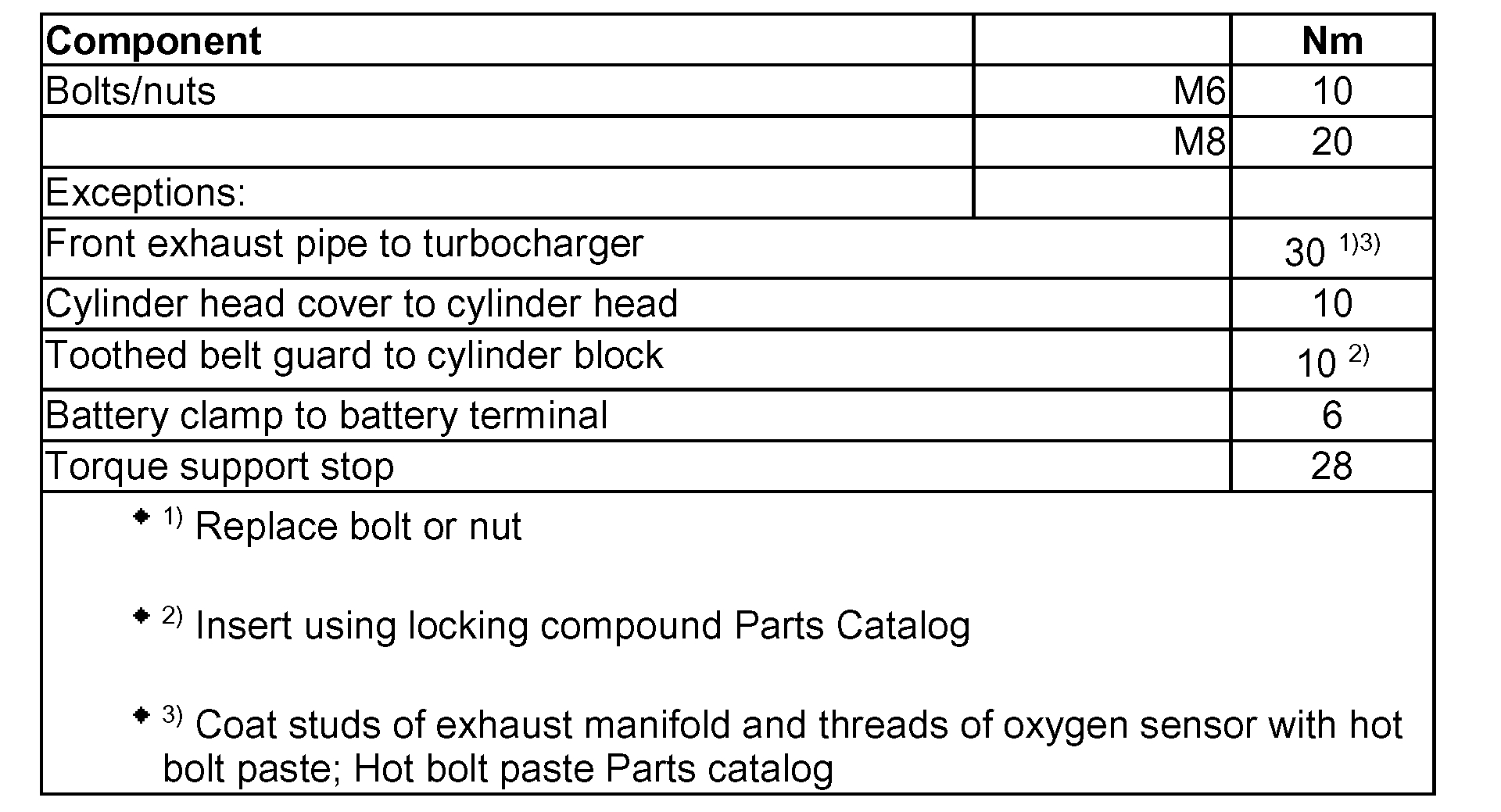
Torque specifications
Picture 24
_______________________________________________
Fuel injector
Fuel Injectors, Removing And Installing
Removing
Remove intake manifold and fuel rail.
Removing fuel injectors, in the event that they are stuck in the fuel rail
Carefully pull fuel injectors out of the fuel rail.
Removing fuel injectors, in the event that they are stuck in the cylinder head
Special tools, testers and auxiliary items required
Picture 25
- Tool set with puller T10133 Tool Set T10133
Remove intake manifold and fuel rail.
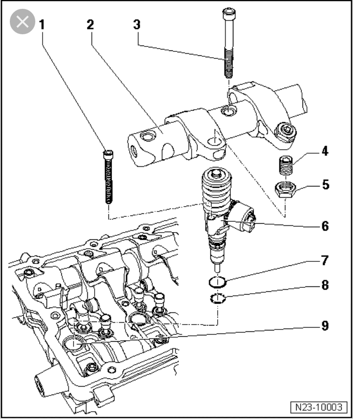
Picture 26
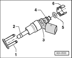
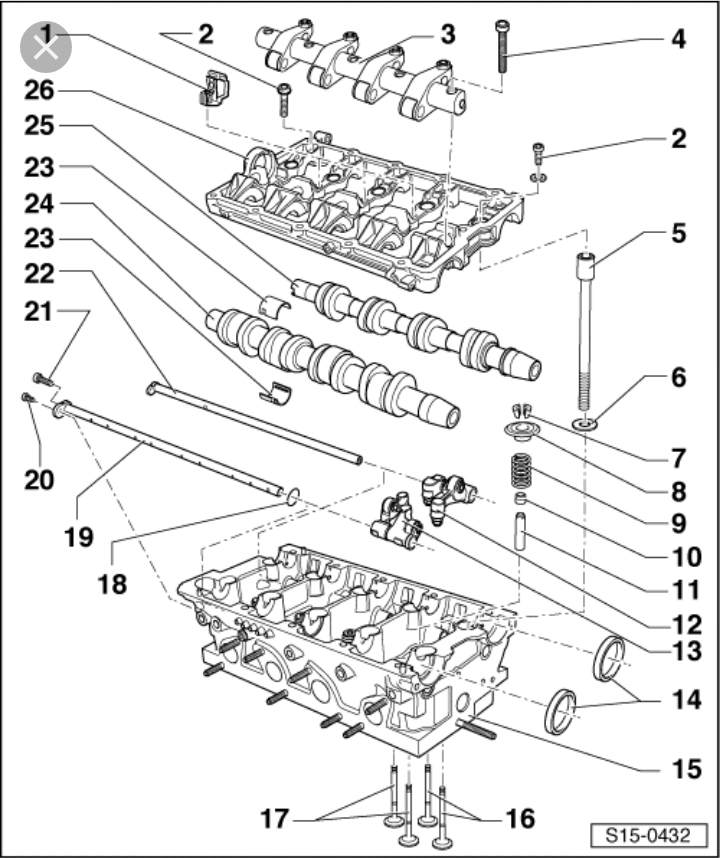
The illustration shows the fuel injector.
1 - Radial compensation, replace if damaged
2 - Combustion chamber sealing ring (Teflon sealing ring). Replace the sealing ring once removed. The sealing ring must not be greased or handled with any other lubricants when installing.
3 - Groove on fuel injector
4 - Spacer ring, replace if damaged
5 - O-ring (replace, coat lightly with clean engine oil when installing)
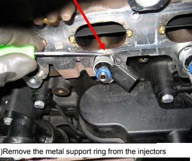
6 - Support ring (via this support ring, the fuel rail utilizes the force to hold the fuel injector in place in the cylinder head).
Picture 27
NOTE: With fuel injector installed, the radial adjustment - 1 - is clipped into the support ring - 6 -. To remove the fuel injector, the support ring must be separated from the fuel injector in order to install the puller T10133/2 into the indentation on the fuel injector - 3 -.
- Cover open intake channels with a clean rag.
- Disconnect electrical harness connector at fuel injector that is to be removed.
Picture 28
- Bend retaining tabs of radial compensation to the side using a screwdriver and pull off support ring from fuel injector.
Picture 29
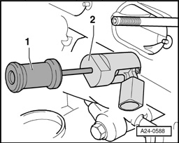
- Assemble the slide hammer T10133/3 - 1 - and the injector puller T10133/2 - 2 -. Then, guide the puller T10133/2 into the groove on the fuel injector and carefully drive the fuel injector out. It is possible that this will destroy the radial compensation (retaining tabs break). This must be replaced when re-installing fuel injector.
NOTE: The combustion chamber seal must always be replaced before re-installing the fuel injector.
__________________________
Fuel Rail
Fuel Rail, Removing and Installing
Vehicle Powertrain Management Fuel Delivery and Air Induction Fuel Rail Service and Repair Removal and Replacement Fuel Rail, Removing and Installing
FUEL RAIL, REMOVING AND INSTALLING
Fuel Rail, Removing And Installing
If fuel rail is to be replaced, the Intake Manifold Runner Position Sensor G336 must be adapted to the Engine Control Module (ECM) J623 again, "Guided Functions"
NOTE: Intake manifold must be removed.
- Remove hoses from EVAP canister.
- To do so, open hose clamp - 1 -.
Picture 30
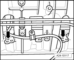
- Remove both bolts - arrows - from fuel rail.
- Remove hose connection 1 from intake manifold and remove both bolts - arrows -.
Picture 31
- Remove both fuel lines - 2 and 3 -.
- Carefully pry off linkage from Intake Flap Motor V157 - 4 -.
Picture 32
- Remove Intake Flap Motor V157 - 5 -.
Picture 33
- Pry fuel rail off from the intake manifold via the retaining tabs - arrows -.
- Remove fuel rail from intake manifold.
Installing
- Installation is in reverse order of removal.
- Install intake manifold.
Let me know if this helps or if you have other questions.
Take care,
Joe
Images (Click to make bigger)
Friday, February 22nd, 2019 AT 11:23 PM