Check the connector and the sensor for any damaged pins. Make sure the connection is tight.
Roy
CIRCUIT DESCRIPTION
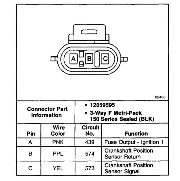
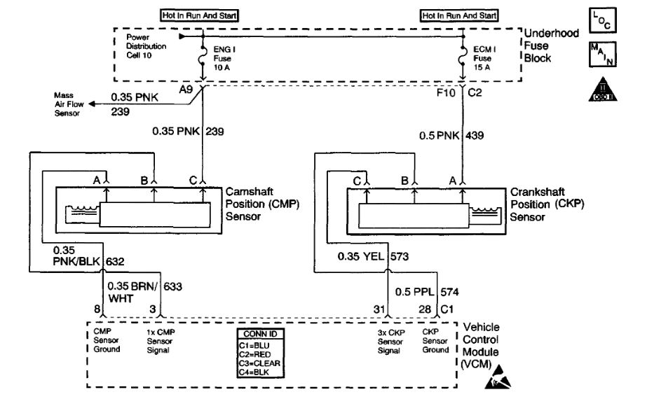
The Crankshaft Position (CKP) sensor is a sensor designed to detect changes in a magnetic field. The control module supplies the CKP sensor a signal and ground circuits. Ignition voltage is supplied to the sensor by an independent circuit. The CKP sensor produces a magnetic field whenever the ignition is ON. The CKP sensor is mounted near a reluctor wheel that is attached to the crankshaft. When the crankshaft rotates, when the engine is cranking or running, the toothed reluctor wheel changes the magnetic field. The CKP sensor converts each change in the magnetic field into a PULSE. The number of teeth on the reluctor wheel determines how many pulses the CKP sensor detects per crankshaft rotation. The CKP sensor signal is used in order to determine the engine speed, the crankshaft position, and to detect misfire.
If a loss of the CKP signal or an erratic signal is detected by the VCM while the engine is running, this DTC will be set.
CONDITIONS FOR RUNNING THE DTC
The MAF is 5 g/s or more.
CONDITIONS FOR SETTING THE DTC
^ The measured change in engine speed is more than 1,000 RPM during a 125 ms time period, or
^ The measured engine speed is 0 RPM and 4 or more camshaft position sensor pulses have occurred over a period of 2 to 3 seconds
ACTION TAKEN WHEN THE DTC SETS
^ The control module illuminates the Malfunction Indicator Lamp (MIL) if a failure is detected during 2 consecutive key cycles.
^ The control module sets the DTC and records the operating conditions at the time the diagnostic failed. The failure information is stored in the scan tool Freeze Frame and Failure Records.
CONDITIONS FOR CLEARING THE MIL OR DTC
^ The control module turns OFF the MIL after 3 consecutive drive trips when the test has run and passed.
^ A history DTC will clear if no fault conditions have been detected for 40 warm-up cycles. A warm-up cycle occurs when the coolant temperature has risen 22°C (40°F) from the startup coolant temperature and the engine coolant reaches a temperature that is more than 70°C (158°F) during the same ignition cycle.
^ Use a scan tool in order to clear the DTCs.
DIAGNOSTIC AIDS
Inspect the face of the CKP sensor for metallic particles. This could result in an intermittent DTC.
Check for the following conditions:
^ A chipped or damaged reluctor wheel
^ An incorrect reluctor wheel
^ The incorrect alignment of the CKP sensor to the reluctor wheel
^ Excessive crankshaft end play
^ Refer to Symptoms. See: Computers and Control Systems > Symptom Related Diagnostic Procedures
An intermittent may be caused by any of the following conditions:
^ A poor connection
^ Rubbed through wire insulation
^ A broken wire inside the insulation
Thoroughly inspect any circuitry that is suspected of causing the intermittent complaint. Refer to Testing for Intermittent and Poor Connections in Diagrams.
If a repair is necessary, refer to Wiring Repairs or Connector Repairs in Diagrams.
Sep 24, 2018 at 2:29 PM