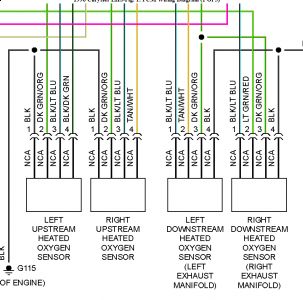
TEST TC-130A - RIGHT DOWNSTREAM O2 SENSOR STAYS AT CENTER 1. Start engine. Allow engine to reach normal operating temperature. Using scan tool, set engine speed to 1500 RPM. Using scan tool, read right downstream O2 sensor state. If right downstream O2 sensor state is switching once every 10 seconds, go to next step. If right downstream O2 sensor state is not switching once every 10 seconds, go to step 5). 2. While monitoring scan tool display, wiggle right downstream O2 sensor wiring harness. If right downstream O2 sensor state locked at center at any time, repair wiring harness as necessary where wiggling caused problem to appear. Perform TEST VER-5A. If right downstream O2 sensor state did not lock at center at any time, go to next step. 3. Condition to set trouble code is not present at this time. RIGHT DOWNSTREAM O2 SENSOR STAYS AT CENTER DTC sets if right downstream O2 sensor signal voltage stays .39-.52 volt during the trip. PCM pulls sensor voltage to 5 volts for 30 seconds and monitors sensor voltage. If voltage stays at 5 volts, this DTC will set indicating no activities. Possible causes are: O2 sensor output wire open, O2 sensor ground circuit open, O2 sensor failure or Powertrain Control Module (PCM) failure. Go to next step. 4. Inspect all related wiring and connectors and repair as necessary. If no problems were found with wiring and connectors, see INACTIVE TROUBLE CODE CONDITION . Test is complete. Perform TEST VER-5A. If related wiring and connectors were repaired, perform TEST VER-5A. 5. Turn ign off. Disconnect downstream sensor connector. Using scan tool in ohmmeter mode, check resistance of right downstream O2 sensor connector (harness side) sensor ground circuit. See RIGHT DOWNSTREAM O2 SENSOR CONNECTOR WIRE ID (HARNESS SIDE) . If resistance is 5 ohms or less, go to next step. If resistance is more than 5 ohms, repair open to sensor ground circuit. See RIGHT DOWNSTREAM O2 SENSOR CONNECTOR WIRE IDENTIFICATION (HARNESS SIDE) table. Perform TEST VER-5A. 6. Connect a jumper wire between right downstream O2 sensor connector (harness side) between signal circuit and battery positive terminal. Turn ignition on. Using scan tool, read right downstream O2 sensor voltage. If voltage is one volt or less, go to next step. If voltage is more than one volt, replace right downstream O2 sensor. Perform TEST VER-5A. 7. Disconnect jumper wire. Turn ign off. Disconnect Powertrain Control Module connector. Using external ohmmeter, check resistance of right downstream O2 sensor signal circuit between right downstream O2 sensor connector (harness side) and PCM connector. See RIGHT DOWNSTREAM O2 SENSOR CONNECTOR WIRE ID (HARNESS SIDE) and PCM CONNECTOR WIRE IDENTIFICATION table. If resistance is less than 5 ohms, replace PCM. Perform TEST VER-5A. If resistance is 5 ohms or more, repair open right downstream O2 sensor signal circuit. Perform TEST VER-5A. NOTE: For connector terminal ID, see CONNECTOR IDENTIFICATION Directory. For wiring diagram, see WIRING DIAGRAMS article. NOTE: Vehicle is equipped with left and right downstream O2 sensor.
1/1/2010 ...This procedure applies if you have been sent here from diagnostic tests and have just attempted to simulate the condition that initially set the Diagnostic Trouble Code (DTC). The following additional checks may assist in identifying a possible intermittent problem: ï¬ Visually inspect related wiring harness connectors for broken, bent, pushed out or corroded terminals. ï¬ Visually inspect related wiring harnesses for chafed, pierced or partially broken wires. ï¬ Check all pertinent Technical Service Bulletins (TSBs).
3.3 has two downstream 02's one on each side, for a total of 4 o2 sensors...

Jan 1, 2010 at 1:38 PM