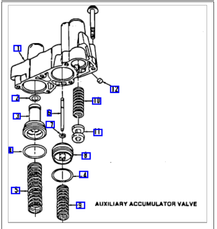
This happens when the accumulator tension spring breaks not slowing the shift plunger down.
Here is what the book says, if you want to see what it looks like there is a image below.
SENSORS & SWITCHES
The PCM/TCM controls upshifts and downshifts based on coolant temperature, transmission temperature, system voltage, throttle position, transmission oil pressure switches, and transmission output and input speed sensors. I would check for any fault codes stored it may be an electrical fault.
Shift Solenoids "A" & "B"
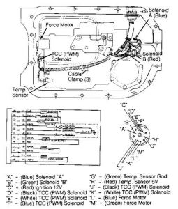
Transmission is shifted up or down by 2 electric solenoids. Both solenoids are located on valve body. See Fig. 1. Ignition power is supplied to each solenoid by the transmission fuse. Solenoid "A" controls hydraulic pressure to 1-2 and 3-4 shift valves. Solenoid "B" controls hydraulic pressure to 2-3 shift valve.
Force Motor
Force motor solenoid has a spool valve and operates pressure regulator valve. See Fig. 1. The computer sends a frequency signal to the force motor to regulate hydraulic line pressure. The frequency signal (duty cycle) is measured with a dwell meter or lab scope. When the duty cycle is zero, line pressure is at maximum, and force motor draws zero amp. When the duty cycle is 40%, line pressure is at minimum, and force motor draws 1.1 amps at 4-5 volts.
TCC Solenoid
This solenoid is used to control TCC apply valve. The computer sends a frequency signal to the TCC solenoid to gradually apply or release the TCC. See Fig. 1.
Fig. 1: Locating Transmission Solenoids, Sensors & Switches
The PCM/TCM constantly monitors all electrical circuits. If the PCM/TCM detects circuit problem(s) or out-of-range sensor(s), a trouble code(s) will be recorded in computer memory. If problem continues for a preset time, the TRANS or SERVICE ENGINE SOON light will glow.
If the TRANS or SERVICE ENGINE SOON light is always on, trouble code(s) is currently being detected. If the TRANS or SERVICE ENGINE SOON light is off, but PCM/TCM has detected a circuit or sensor problem, trouble code(s) will be stored in computer memory.
Stored trouble codes may be retrieved from PCM/TCM memory using "Scan" tool or TRANS or SERVICE ENGINE SOON light. See appropriate RETRIEVING CODES procedure under ELECTRONIC SELF-DIAGNOSTICS.
NOTE:For complete PCM/TCM testing and diagnosis, see appropriate TESTS W/CODES article in the ENGINE PERFORMANCE section:
For Diesel Vehicles, see TESTS W/CODES - DIESEL
For Transmission Codes, see TESTS W/CODES - TRANSMISSION
For V6 Equipped Vehicles, see TESTS W/CODES - V6
For V8 Equipped Vehicles, see TESTS W/CODES - V8
ELECTRONIC SELF-DIAGNOSTICS
NOTE:To test electronic control of transmission solenoids without using self-diagnostics, go to COMPONENT TEST CHARTS (NO CODES) under ELECTRONIC TESTING. After repairs are made, trouble codes should be erased from computer memory. See CLEARING TROUBLE CODES.
RETRIEVING CODES (WITHOUT "SCAN" TOOL)
Turn ignition on. DO NOT start engine. TRANS or SERVICE ENGINE SOON light should glow. Locate Assembly Line Data Link (ALDL) connector under dash, on driver's side of vehicle. Turn ignition on with engine not running. Connect jumper wire from terminal "B" (diagnostic terminal) to terminal "A" (ground terminal) of ALDL connector. See Fig. 2.
NOTE:Connecting terminals "A" and "B" of ALDL connector with engine running will cause fuel injected vehicles to enter field service mode. The TRANS or SERVICE ENGINE SOON light will not flash codes if this is done.
Fig. 2: Identifying ALDL Connector Terminals
Courtesy of GENERAL MOTORS CORP.
TRANS or SERVICE ENGINE SOON light should begin flashing codes. Each code will be repeated 3 times. Code 21 is identified by 2 flashes, a short pause followed by one flash; Code 53 is identified by 5 flashes, a short pause followed by 3 flashes. Trouble codes are separated by slightly longer pauses.
Trouble codes are displayed in numerical order. Each code is displayed 3 times. Codes will continue to repeat as long as ALDL test terminal is grounded.
If codes are not flashed, or TRANS or SERVICE ENGINE SOON light does not glow, self-diagnostics will not work. See CHART A-1 under DIAGNOSTIC CHARTS. If TRANS or SERVICE LIGHT SOON light glows steadily, see CHART A-2 under DIAGNOSTIC CHARTS. To exit diagnostic mode, turn ignition off, and remove jumper wire from ALDL connector.
NOTE:Trouble codes will be recorded at various operating times. Some codes require operation of sensor or switch for 5 seconds; others may require operation for 5 minutes or longer at normal operating temperature, road speed and load. Therefore, some codes may not set in a service bay operational mode, but may require road testing vehicle in order to duplicate condition under which code will set.
RETRIEVING CODES (WITH "SCAN" TOOL)
NOTE:To read trouble codes and check system voltages on serial data line, plug "Scan" tool into ALDL.
The "Scan" tool is a specialized tester which, when plugged into ALDL, can be used to diagnose on-board computer control systems by providing instant access to circuit voltage information without need to crawl under dash or hood to backprobe sensors and connectors.
"Scan" tools may also furnish information on status of output devices (solenoids and relays). However, status parameters are only an indication that output signals have been sent to devices by the control module. It does not indicate if devices have responded properly to that signal. This will need to be checked at output device using a voltmeter or test light.
NOTE:Code 12 should always exist when ALDL is grounded with key on and engine off, but may not be indicated by all makes of "Scan" tools.
If trouble code is not present, this is not an indication that is no problem. Driveability-related problems with codes displayed occur about 20 percent of the time, while driveability problems without codes occur about 80 percent of the time.
Out-of-specification sensors WILL NOT set trouble code, but WILL cause driveability problems. Using "Scan" tool is the easiest method of checking sensor specifications and other data parameters. Intermittent wiring problems may be identified by wiggling wiring harnesses and connections (key on, engine off) while observing "Scan" tool.
NOTE:If erroneous voltage signals are suspected, it will be necessary to verify tester information using digital voltmeter and wiring schematic. If non-existent codes are displayed, turn ignition off, remove tester, turn ignition on, and ground ALDL test terminal "B". The same codes should be retrieved whether "Scan" tool or TRANS or SERVICE ENGINE SOON light is used.
TROUBLE CODE DEFINITION
PCM/TCM TROUBLE CODE DEFINITION
Code No.Circuit Affected
12 (1)No RPM Reference Pulse
14Coolant Temperature High
15Coolant Temperature Low
21Throttle Position Switch Voltage High
22Throttle Position Switch Voltage Low
24Output Speed Sensor Circuit
28Pressure Switch Manifold Problem
53System Voltage Too High
39(2) TCC Problem
58Transmission Temperature High
59Transmission Temperature Low
68Overdrive Ratio Error Problem
73Force Motor Current Problem
75System Voltage Too Low
81Shift Solenoid "B" Circuit Error
82Shift Solenoid "A" Circuit Error
83TCC Solenoid Circuit Error
85Undefined Ratio Error Problem
86Low Ratio Error Problem
87High Ratio Error Problem
(1)Display of a Code 12 is normal when no reference pulses are received by control module (engine not running).
(2)Code 39 indicates TCC problem may be present. For complete information, see GM TORQUE CONVERTER CLUTCH article.
NOTE:Only transmission-related trouble codes are listed. If other trouble codes are present, see appropriate article in the ENGINE PERFORMANCE section.
Check out the diagrams (Below)
Please let us know what happens.
Cheers
Sep 16, 2010 at 6:17 PM