I never use the splice generic, any contamination on these wires cause problems...test this way first...
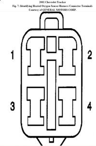
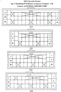
Circuit Description Heated Oxygen (HO2S) No. 1 heater increases the amount of time sensor spends in closed-loop fuel control operation or catalyst monitoring operation. Oxygen sensor heater greatly reduces amount of time required for HO2S No. 1 to become active. Oxygen sensor heater is required by post-catalyst HO2S No. 2 in order to maintain high operating temperatures. Heater helps provide accurate oxygen content readings of engine exhaust by HO2S. Code Enable Criteria Conditions for running DTC: ï¬ Engine is running. Conditions for setting DTC: ï¬ HO2S heater current is greater than 5.3 amps or less than 0.15 amp when heater is on. ï¬ HO2S heater voltage is greater than 13.8 volts or less than 8.7 volts when heater is on. ï¬ HO2S heater voltage is 6 volts with heater off. ï¬ One of the above condition is present for 3 seconds. Diagnostic Procedures 1. Perform diagnostic system check. See POWERTRAIN DIAGNOSTIC SYSTEM CHECK under SELF-DIAGNOSTIC SYSTEM. After performing diagnostic system check, go to next step. 2. Turn ignition off. Disconnect HO2S 1 harness connector. Turn ignition on, with engine off. Using a test light connected to ground, probe HO2S 1 harness connector terminal No. 4 (Black/White wire). See Fig. 7 . If test light illuminates, go to next step. If test light does not illuminate, go to step 7 . 3. Turn ignition off. Using a DVOM, check resistance between HO2S 1 harness connector terminals No. 3 (Black/White wire) and No. 4 (Gray wire). Resistance should be 4.5-5.7 ohms at 68 °F (20 °C ) on HO2S with warm-up TWC or 11.7-15.6 ohms at 68 °F (20 °C ) on HO2S without warm-up TWC. If resistance is as specified, go to next step. If resistance is not as specified, go to step 8 . 4. Connect test light between battery voltage and HO2S harness connector terminal No. 3 (Gray wire). Start engine. If test light illuminates only when engine is running, see DIAGNOSTIC AIDS . If test light does not illuminate when engine is running, go to next step. 5. Turn ignition off. Reconnect HO2S harness connector. Disconnect PCM harness connector C2. Turn ignition on, with engine off. Check voltage at PCM harness connector C2 terminal No. 4 (Gray wire). See Fig. 3 or Fig. 4 . If voltage reading is greater than 10 volts, go to step 10 . If voltage reading is not greater than 10 volts, go to next step. 6. Turn ignition off. Repair open or short to ground in Gray wire between HO2S 1 and PCM. After repairs, go to step 11 . 7. Turn ignition off. Repair open in Black/White wire between HO2S 1 and fuse block. After repairs, go to step 11 .
8. Check for faulty connection at HO2S 1 harness connector. Repair as necessary. After repairs, go to step 11 . If connection is okay, go to next step. 9. Replace HO2S 1. After replacing sensor, go to step 11 . 10. Turn ignition off. Replace PCM. Perform PCM relearn procedure. See POWERTRAIN CONTROL MODULE under PROGRAMMING. After replacing PCM, go to next step. 11. Turn ignition on, with engine off. Using scan tool, clear DTCs. Turn ignition off for 30 seconds. Start engine and operate vehicle within FREEZE FRAME conditions or until HO2S heater diagnostic has run. If DTC runs and passes, go to next step. If DTC resets, go to step 2 . 12. Using scan tool, observe the stored information and Capture Info. If scan tool displays any undiagnosed DTCs, diagnosed affected DTCs. See DIAGNOSTIC TROUBLE CODE DEFINITIONS . If no DTC are displayed, system is okay. Diagnostic Aids Check for a poor PCM electrical connection. An intermittent malfunction may be caused by a poor connection, rubbed-through wire insulation, or a wire broken inside insulation. Check harness connectors for backed-out terminals, improper mating, broken locks, improperly formed or damaged terminals, or poor terminal-to-wire connections before component replacement.
This info is for 2.0 engine.
Aug 23, 2009 at 11:09 AM