DTC P0336
Circuit Description
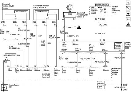
The circuit uses 2 different types of crankshaft position (CKP) sensors. The CKP sensor B is connected directly to the ignition control (IC) module, and consists of the following circuits:
• The CKP sensor 1 signal circuit
• The low reference circuit
The CKP sensor A connects directly to the powertrain control (PCM) module, and consists of the following circuits:
• The 12-volt reference circuit
• The medium resolution engine speed signal circuit
• The low reference circuit
If the PCM detects an incorrect number of CKP pulses, DTC P0336 sets.
Conditions for Running the DTC
The engine is running, and 3 X reference pulses are being received for a minimum of 3 seconds.
Conditions for Setting the DTC
The ratio of 24 X reference pulses to 3 X reference pulses received by the PCM is incorrect.
Action Taken When the DTC Sets
• The control module illuminates the malfunction indicator lamp (MIL) on the second consecutive ignition cycle that the diagnostic runs and fails.
• The control module records the operating conditions at the time the diagnostic fails. The first time the diagnostic fails, the control module stores this information in the Failure Records. If the diagnostic reports a failure on the second consecutive ignition cycle, the control module records the operating conditions at the time of the failure. The control module writes the operating conditions to the Freeze Frame and updates the Failure Records.
Conditions for Clearing the MIL/DTC
• The control module turns OFF the malfunction indicator lamp (MIL) after 3 consecutive ignition cycles that the diagnostic runs and does not fail.
• A current DTC, Last Test Failed, clears when the diagnostic runs and passes.
• A history DTC clears after 40 consecutive warm-up cycles, if no failures are reported by this or any other emission related diagnostic.
• Clear the MIL and the DTC with a scan tool.
Diagnostic Aids
DTC P0336 can be caused by secondary components leaking high voltage into the ignition control (IC) module. Inspect for the following conditions:
• Incorrect harness routing near secondary ignition components.
• Ignition coil arcing to wiring harness or IC module, inspect ignition coils for cracks, carbon tracking, or other signs of damage.
• Secondary ignition wires arcing to wiring harness.
• If the DTC is determined to be intermittent refer to Intermittent Conditions in Wiring System.
Test Description
The numbers below refer to the step numbers on the diagnostic table.
If sent here from DTC P0327 proceed with DTC P0336 Diagnostic even if P0336 has not failed this ignition.
The 24X RPM on the scan tool should change each time the medium resolution engine speed signal circuit is touched.
Step
Action
Values
Yes
No
Schematic Reference: Engine Controls Schematics
Connector End View Reference: Engine Controls Connector End Views or Powertrain Control Module Connector End Views
1
Did you perform the Diagnostic System Check-Engine Controls?
--
Go to Step 2
Go to Diagnostic System Check - Engine Controls
2
Start the engine.
Observe the 24 X parameter with a scan tool.
Does 24 X RPM vary with engine speed up to approximately 1,600 RPM?
--
Go to Step 3
Go to Step 4
3
Observe the Freeze Frame/Failure Records data for this DTC.
Turn OFF the Ignition.
Start the engine.
Operate the vehicle within the Conditions for Running the DTC. You may also operate the vehicle within the conditions that you observed from the Freeze Frame/Failure Records.
Does the DTC fail this ignition?
--
Go to Step 4
Go to Diagnostic Aids
4
Important: A short to ground on the cam or crankshaft position sensor 12-volt reference circuit can cause DTC 327 to set. Test this circuit for a short to ground before proceeding with this diagnostic table. Refer to Circuit Testing and Wiring Repairs in Wiring Systems.
Turn OFF the ignition.
Disconnect the CKP sensor A connector.
Turn ON the ignition, with the engine OFF.
Measure the voltage from the 12-volt reference circuit of the CKP sensor A to a good ground with the DMM.
Does the voltage measure near the specified value?
B+
Go to Step 6
Go to Step 5
5
Test the 12-volt reference circuit of the CKP sensor A for a short to ground or an open. Refer to Wiring Repairs in Wiring Systems.
Did you find and correct the condition?
--
Go to Step 16
Go to Step 12
6
Connect a test lamp to battery positive voltage.
Touch the CKP sensor A low reference circuit.
Does test lamp illuminate?
--
Go to Step 8
Go to Step 7
7
Test the low reference circuit of the CKP sensor A for an open or high resistance. Refer to Wiring Repairs in Wiring Systems.
Did you find and correct the condition?
--
Go to Step 16
Go to Step 12
8
Observe the 24X parameter on the scan tool.
Connect a 5-amp fused jumper wire to battery positive voltage, momentarily touch the medium resolution engine speed signal circuit 5 times for a duration of 1 second each.
Does 24 X RPM change EACH time the signal circuit is touched?
--
Go to Step 13
Go to Step 9
9
Did the fuse in the jumper wire open?
--
Go to Step 11
Go to Step 10
10
Test the medium resolution engine speed signal circuit of the CKP sensor A for the following conditions:
• A short to voltage
• An open
• High resistance
Refer to Wiring Repairs in Wiring Systems.
Did you find and correct the condition?
--
Go to Step 16
Go to Step 12
11
Test the medium resolution engine speed signal circuit of the CKP sensor A for a short to ground. Refer to Wiring Repairs in Wiring Systems.
Did you find and correct the condition?
--
Go to Step 16
Go to Step 12
12
Test for an intermittent and for a poor connection at the PCM. Refer to Testing for Continuity , and Testing for Intermittent Conditions and Poor Connections in Wiring Systems.
Did you find and correct the condition?
--
Go to Step 16
Go to Step 14
13
Test for an intermittent and for a poor connection at the CKP sensor A. Refer to Testing for Continuity and Wiring Repairs in Wiring Systems.
Did you find and correct the condition?
--
Go to Step 16
Go to Step 15
14
Replace the PCM. Refer to Powertrain Control Module Replacement .
Did you complete the replacement?
--
Go to Step 16
--
15
Replace CKP sensor A. Refer to Crankshaft Position Sensor Replacement .
Did you complete the replacement?
--
Go to Step 16
--
16
Clear the DTCs with a scan tool.
Turn OFF the ignition for 30 seconds.
Start the engine.
Operate the vehicle within the Conditions for Running the DTC. You may also operate the vehicle within the conditions that you observed from the Freeze Frame/Failure Records.
Did the DTC fail this ignition?
--
Go to Step 2
Go to Step 17
17
Observe the Capture Info with a scan tool.
Are there any DTCs that have not been diagnosed?
--
Go to Diagnostic Trouble Code (DTC) List
System OK
Feb 18, 2008 at 8:40 PM