I don't have access to service information for that model. Is this vehicle in North America? Would you know if another model is similar? My listings start with 320i, then multiple 325 330, and 525 models.
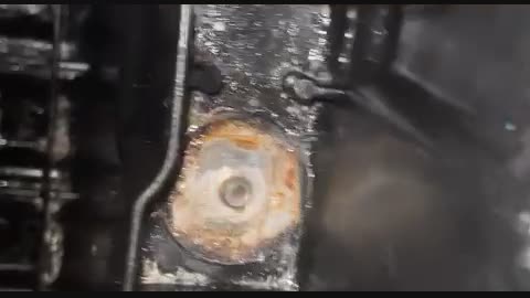
Thank you for the dandy photo. Is this the under-hood fuse box? All my models show something quite different, plus, BMW doesn't release their wiring diagrams, so I can't tell what the other cable on the right is for.
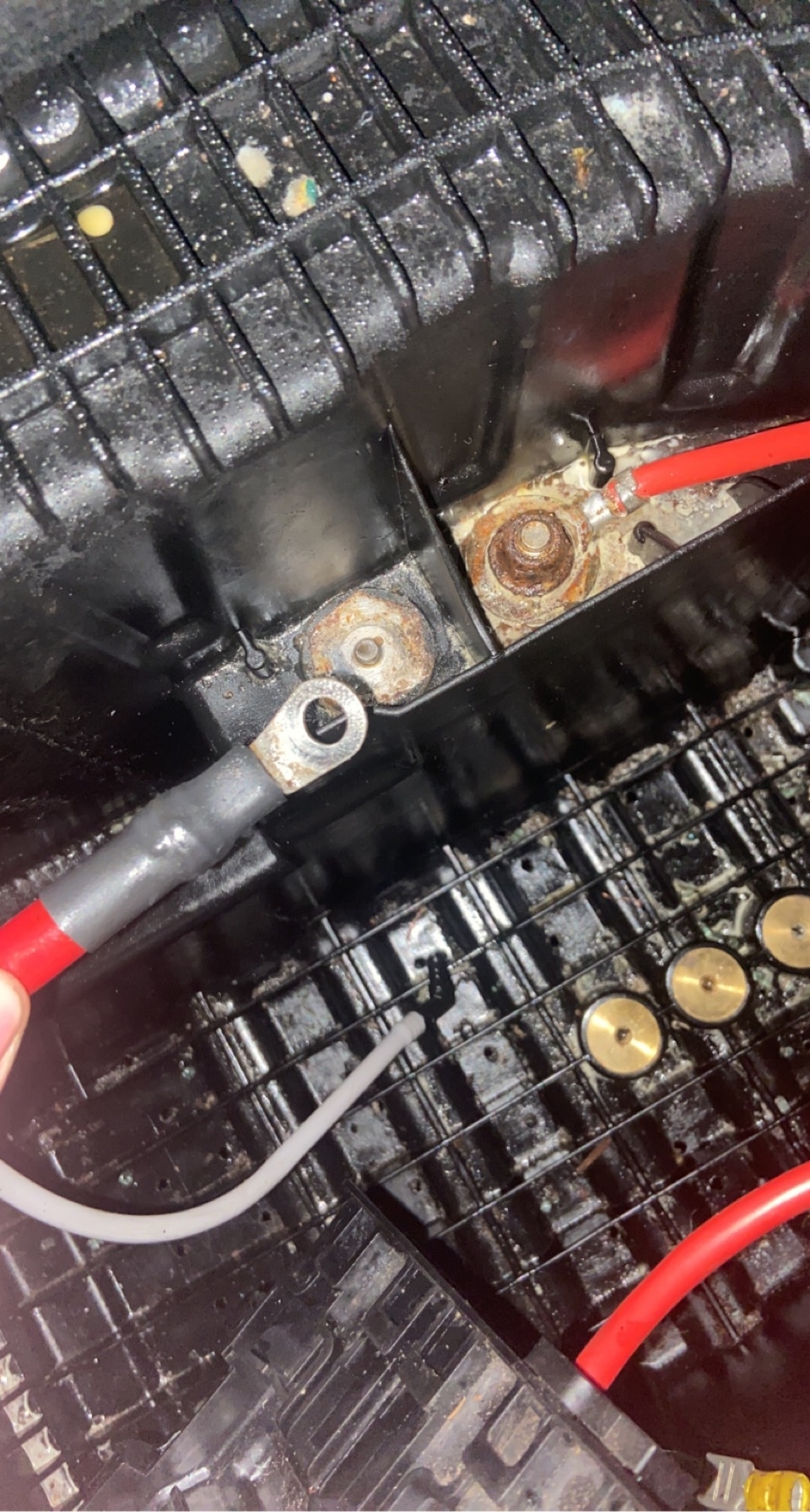
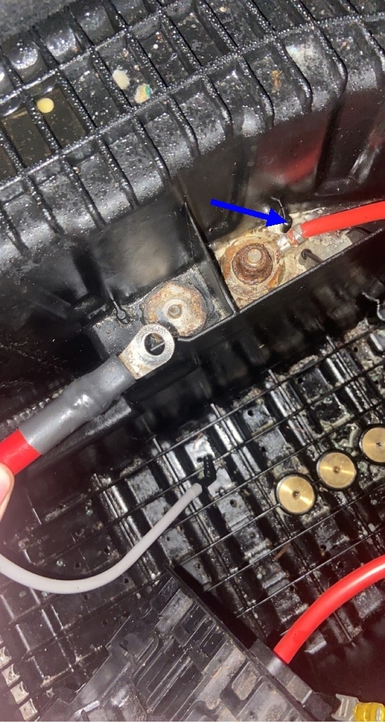
My next question has to do with the four fingers, (blue arrow). I think those are just to stop the cable from turning while the nut is being tightened. They could also be to hold terminals in place during assembly. On the right it looks like a solid metal plate is slid under the two fingers, then the bolt / stud is run through it. I don't see that on the left side. The point is if there is a metal plate slid under the fingers, that would imply that plate can be lifted up and that is a stud coming through it, not a rivet. Well, not really a rivet. More of a pressed-in bolt that won't easily slide out.
I see two ways of attacking this. The best way is to take the assembly apart to see what is on the other side of that stud. That could be a bolt that can be tapped or pressed out, then a new one popped in. When it is designed like that, the original bolt usually will have serrations under the head to keep it from spinning. You won't find a replacement like that unless you have another assembly you can take apart. Instead, use a regular bolt that slips through easily, then put a nut on it first to hold that bolt head to the metal strip that's under it. Make that nut very tight so it doesn't loosen whenever you have to remove or replace the cable. If necessary, place a washer on top of that nut, then the cable, another washer, then the last nut.
If this method works, watch for how tall the head of the new bolt is compared to the piece you removed. It is common for other buss bars or circuit boards to be located right under it where a head that's too tall might hit something when it is reassembled. If that could be an issue, grind the head down first, then I like to cover the area with a piece of hard plastic. Consider visiting a body shop and getting a smashed plastic inner fender liner or a piece of one. That stuff can be cut with a utility knife. Thick cardboard, or "card stock" can be used too, but that is susceptible to water damage and wear from vibration.
I'm going on the assumption this is a fuse box under the hood. It looks like water is able to puddle around those studs, so consider coating them with dielectric grease after the cables have been attached. We need to have a solid electrical connection to prevent intermittent problems in the future. Use a rotary tool with some type of small sanding disc to clean the area up where the cable makes contact, and clean both sides of the cable's terminal. I would normally recommend peeling the cable's insulation back just enough to check for corrosion of the copper strands of wire, but with that black heat-shrink tubing, that should not be necessary. If you see what looks like hot-melt glue that has oozed out of that heat-shrink tubing, that seals out moisture. If that is standard heat-shrink tubing without the hot-melt glue, it still does a fairly good job, but it is possible for water to sneak inside it if water pools around it at times.
The less-preferred method would be to drill a hole into what's left of the stud, tap it, then run in a new, smaller bolt. I find it almost impossible to keep the hole centered. The other problem is the new bolt will be of such a small diameter that you won't be able to tighten it very much. If nothing else will work, and you must replace the assembly, first try drilling the entire bolt out. This should only be a last resort because we don't know what you'll be drilling into, or whether that stud has a head on it that will fall off and possibly short something out inside. I'd feel better doing this if the assembly was apart and you can see what you're drilling through.
The last thing to consider is that other stud on the right. This is where I wish I had a diagram to look at. It is possible those two studs are connected internally. They design it that way to give each cable end a solid connection rather than stacking two terminals on top of each other on one stud. You can determine that by measuring and comparing the voltages on the two studs when fuses are removed, or by measuring the resistance between them, again, when fuses are removed. If you always find continuity or the same voltages at both places, they are likely connected together inside the housing, and you can just move the left cable to the right stud and bolt both of them together. I would sand both terminals nice and flat to increase their contact area as much as possible.
It is also possible there is a fuse between the two studs. This is where you would find 12 volts on the larger, (left) cable, and when touched to its broken stud, you will only find 12 volts on the right cable when the fuse is in place. That second stud will go to 0 volts when the fuse is removed. If you find that, we really don't want to bypass that fuse, so moving the left cable to the right stud is not an option.
When there is a fuse between two large studs like you have here, that is going to be a very high-current fuse, not some little 15 or 20-amp fuse. This is usually for the generator and is often bolted into the fuse box. Expect it be over 100 amps. Bolted terminals are needed for such high current. Little plug-in terminals would overheat.
If I've gotten you partially confused, you're better off not reading further. The following is the least preferred repair and is not something we would do on a customer's car.
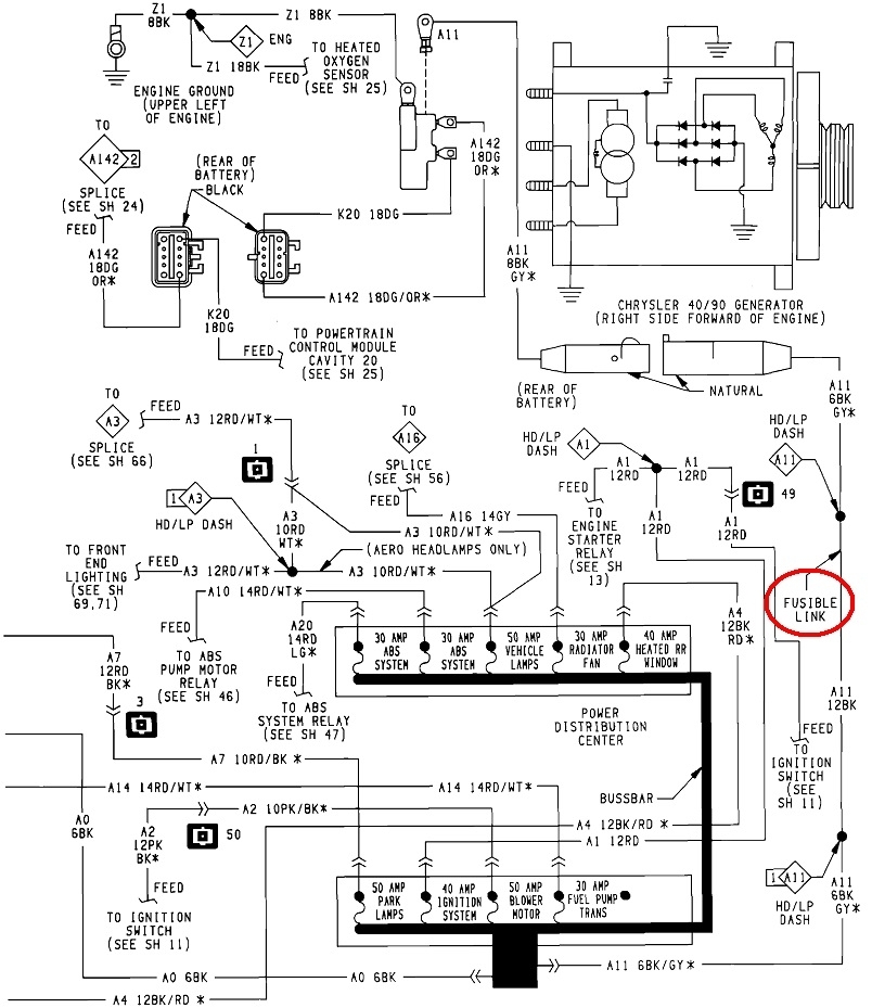
I'm grasping at straws now, but if you do find there is a large fuse between the two studs, and no other repair option works, there is one more modification I can think of. This must absolutely not be done if the right cable feeds the starter motor. I've never seen multiple mechanical fasteners in the high-current side of the starter system, but it needs mentioning. A starter motor will draw too much current for this "fix". To say this a different way, there should be two cables attached at the battery's positive post. The fatter one goes down to the starter motor. The smaller-diameter wire is the left one in your photo. Remember too, this only applies if there is a high-current fuse between the two studs. What I would consider is removing the right cable, then bolting only the left cable to that stud. That will supply current through that large fuse to the fuse box / rest of the car, but it leaves the right cable dead. Again, I'm assuming that one is for the generator. There have been many models where that generator output cable runs right back to the battery, but in the last 45 years or so, that circuit has been fused. Today it is most common to see that high-current bolted-in fuse I mentioned, but on older models, a "fuse link" or "fuse link wire" was used. That is what I would consider for this modification. The second diagram shows the circuit you'll end up with. This is from my '93 Dynasty but it's representative of a lot of different brands and models.
This modification involves running a second wire from the stud on the right, and connecting it to the cable you removed from that stud. We have liability issues to think of too, but this is going to end up similar to many factory designs. First of all, this is not an ordinary wire. Fuse link wires, like the one I circled in red, are of a smaller diameter than the wire it is spliced into, making it the weak link in the chain. In other words, that makes it the fuse device. Second, the insulation will not burn or melt when the wire burns apart. You can buy fuse link wire at any auto parts store. You'll get a piece roughly 12" long which is plenty to cut to make three or four repairs. You only use as much of it as you need.
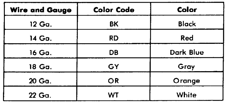
As a cheap alternative, you can get fuse link wires in any pick-your-own-parts salvage yard. The easiest ones to find are on early to mid '90s front-wheel-drive Chrysler products. There will be a bundle of them running around the left strut tower by the driver's side hood hinge area. Their insulation will be a dull color, usually gray, white, or orange. The color denotes the current rating. You can also find one or two fuse links attached to the larger "Battery" terminal on GM starters. Those are typically black or gray. They have nothing to do with the starter system. That stud on the starter is just used as a convenient tie point.
There are two things a fuse link wire protects from in a generator circuit. One is if a metal tool accidentally touches the generator's output terminal and anything metal on the engine at the same time. That puts a direct short across the battery and would make the tool glow orange hot and weld itself in place if it weren't for that fuse. The second condition is if a specific two of the generator's six "diodes" were to short at the same time. That would also put a short across the battery.
Regular bolted-in fuses work just fine with generator circuits, but fuse link wires have a huge advantage in motor circuits. All electric motors draw very high start-up current, then it settles down quickly to its normal running current. Fuse link wires are "slow-blow", or slow-acting fuses. They happily tolerate that high start-up current without blowing unnecessarily.
To continue, the fuse link wire is a normal wire except that it's of a smaller diameter. You work with them just like any other wire. I would attach a universal crimp-style ring terminal to one end, but solder it too for best connection, then seal it with a piece of moisture-proof heat-shrink tubing to give water one less place to sneak in. Once all the contact surfaces are shined up, put the left battery cable on the right stud first so it is against the metal disc or plate on the assembly, then put the new fuse wire's terminal on next, then the nut with perhaps a washer under it.
The other end of the wire goes to the wire you removed from the right stud. You can get away without adding a terminal here. Strip off a good inch of insulation, then wrap that wire around a short bolt to connect them together. This connection must be sealed too, both to keep out water and to prevent it from touching anything metal in that area. The original stud also provided a solid means of support that is lacking now. Look for a place where you can attach a plastic strap to anchor the cable. Without that anchor, the fuse wire will constantly flex from vibration and eventually fail.
This modification gives you back the protection for the generator circuit and it gets power to the fuse box.
Remember, I'm going on the assumption this is the under-hood fuse box and the wire on the right stud is for the generator. Let me know if I have that wrong.
Now to add one more comment to be sure you're thoroughly confused. This has to do with the current rating of that fuse link wire. The most common generator I found for BMW was a 120-amp unit, but I did see a few 90-amp and 150-amp. All of the generator's output current has to pass through that fuse link wire, so it should have a rating of at least 120 amps. The first thing to understand about AC generators is they will always only develop exactly the amount of current that is needed to run the electrical system and to recharge the battery, and no more. Just because it can develop 120 amps, it's only going to develop, . . . 72 amps, if that's what is called for. Almost any fuse link wire will handle that.
There is only one exception to this, meaning only one time the generator will develop its full maximum output current. That is for the three or four seconds when your mechanic performs the "full-load output current test" which is part of every battery / charging system test. As designed, the original fuse or fuse link wire will handle that current. In some applications it is possible to install a generator with a higher capacity. It still will only develop what the electrical system needs, and no more, until that full-load output current test is run, which might be many years from now. That is when, with a higher output generator, it might develop more current than originally designed and blow the fuse. Since that test just lasts a few seconds, just long enough to read the meter, most fuse link wires will tolerate that while still offering protection for the shorts I mentioned.
The last chart shows the color code for the current ratings of fuse link wires.
That last modification should only be used if absolutely nothing else works. I'd rather see you find a replacement assembly first if it comes to that.
Let me know how you'd like to proceed.
Images (Click to enlarge)
Feb 23, 2023 at 2:29 PM