I found the following answer for a brake controller

Tiny
SULLY525
  • MEMBER
  • 2013 CHEVROLET EQUINOX
  • 1.4L
  • 4 CYL
  • 4WD
  • AUTOMATIC
  • 155,000 MILES
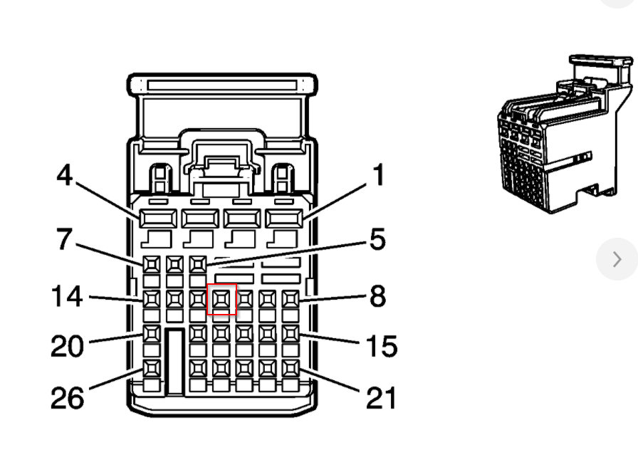
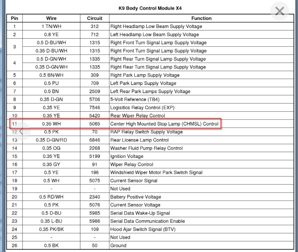
I am trying to hook up a RM -88400 Diode that I purchased from E Trailer on my vehicle listed above. I found the following answer for a brake controller and I am wondering if that is the same wire that I place the diode in line? Look for the black connector (all the connectors are different colors) that has 26 different slots for wires to insert into. In wire position # 11, there will be a white wire that carries the brake stoplight signal. Use the quick connector to tap the red brake controller wire into this circuit, and you will be good to go.
Friday, September 11th, 2020 AT 6:36 PM

6 Replies

Tiny
KASEKENNY
  • MECHANIC
  • 18,907 POSTS
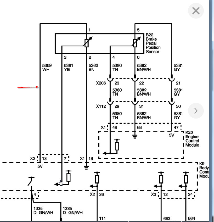
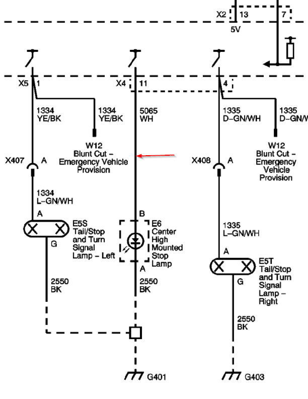
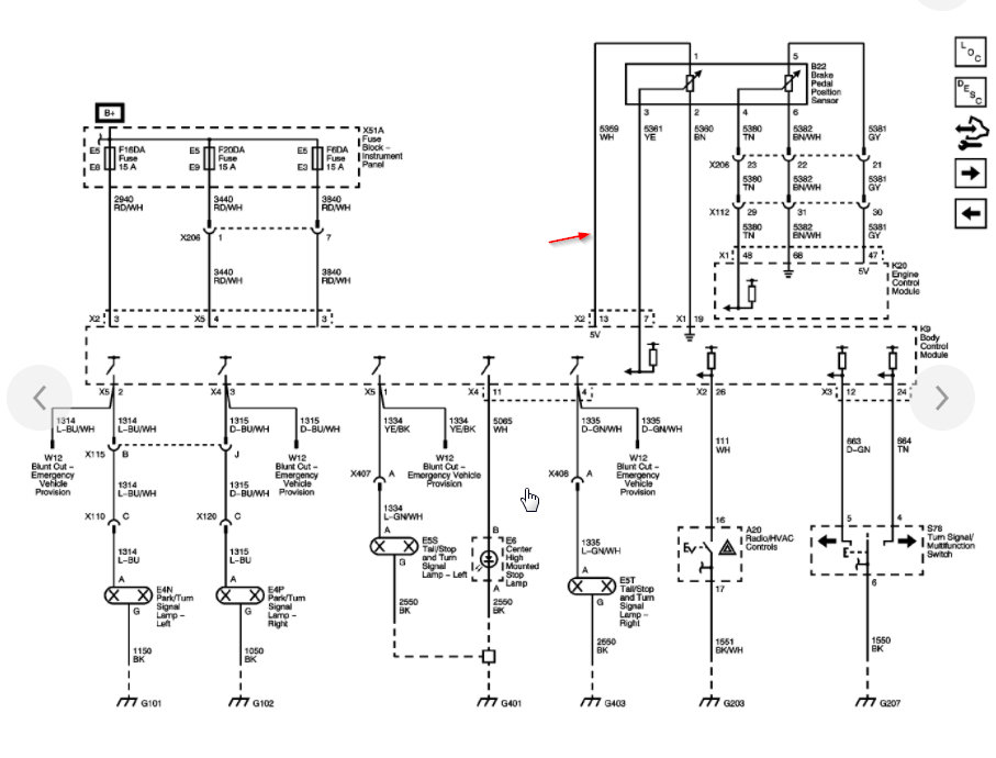
I assume you are talking about the connectors for the body controller? If so, you have two options for white wires but since they mention pin 11 they are not talking about the brake signal. That is the power wire for the third brake light. The brake signal wire is a 5 volt wire from the brake switch so I doubt it is that one.

I attached all the info for this connector and which pin it is. Let me know if I am missing something. Thanks
Was this
answer
helpful?
Yes
No
Friday, September 11th, 2020 AT 7:00 PM
Tiny
JACOBANDNICKOLAS
  • MECHANIC
  • 108,328 POSTS
Hi,

I read your post. The red wire they refer to is what is being added, correct? What are you installing the diode to do? You don't want to add it in the vehicle's circuit. A diode is designed to allow power to travel one direction and not the other.

Let me know.

Joe
Was this
answer
helpful?
Yes
No
Friday, September 11th, 2020 AT 7:11 PM
Tiny
SULLY525
  • MEMBER
  • 3 POSTS
The purpose of a brake light relay kit is to prevent your towed car's brake signal from overriding the turn signal that comes from your RV. When your towed vehicle is properly wired and connected to your RV, its indicator lights will illuminate as you engage the turn signals in your RV. However, if you have only a four-diode system in place, the turn signal will be overridden by your towed car's brake signal as soon as your supplemental braking system presses the towed car's brake pedal. As a result, drivers behind you know only that you're slowing down and not that you are turning.

Installing a brake light relay in your towed vehicle fixes this problem by ensuring that your car's brake signal does not override the RV's turn signal. Therefore, your towed car's lights will function in accordance with your RV at all times.

Normally Open

The diagram and steps shown below demonstrate the installation for normally open applications. Be sure to follow the instructions included with your relay kit for a more detailed process.

Standard Normally Open Installation for Roadmaster Brake-Lite Relay
Remove the blue wire from the kit. This wire is not needed for normally open applications.
Locate the brake-light-switch wire in your towed car.
Remove the brake light fuse.
Cut the brake light wire a few inches away from the "cold" side of the brake light switch.
Attach the relay to the wiring for the RV braking monitor. The diagram above shows where the green wire attaches the relay to either a Roadmaster Even Brake or BrakeMaster system.
Connect the black wire of the relay to the brake light wire near the brake light itself using the included blue butt connector.
Identify a fuse that is only powered when the ignition is in the "run" position and not when it is in the "tow" position. Pull the fuse. Insert the fuse into the slot closest to the fuse blades, then insert the fuse tap into the empty slot in the fuse panel.
Using the attached blue butt connector, connect the red wire from the brake relay to the wire from the fuse tap.
Ground the white wire to your towed vehicle's frame.
Secure the relay with the included wire ties.

My question is: Is the #11, white wire from the BCM the wire I need to use in this case.
Was this
answer
helpful?
Yes
No
Saturday, September 12th, 2020 AT 12:42 AM
Tiny
KASEKENNY
  • MECHANIC
  • 18,907 POSTS
If you take a look at the wiring diagram I attached earlier, you will see that you have a brake pedal position sensor and not a switch. This is different in the fact that your sensor tells the BCM the position of the pedal and the BCM decides where to send power based on that position. A pedal switch that these directions are talking about is basically and on/off switch for the brake lights. So when you press the pedal enough to turn the switch on, it turns the brake lights on. With this vehicle the BCM actually turns the brake lights on.

Based on that, you don't have a "cold" wire coming from the switch because you don't have a switch. What I would suggest is calling the manufacturer of this kit and ask them which wire you will need with a pedal position sensor and we can help identify that if needed.

Let me know if this doesn't make sense. Thanks
Was this
answer
helpful?
Yes
No
+1
Sunday, September 13th, 2020 AT 6:49 PM
Tiny
SULLY525
  • MEMBER
  • 3 POSTS
Thank you. I had already figured that part out. The #11 wire from the BCM has 12V when the brake is depressed but I am not positive that is the wire I need to tie into. I like your suggestion of trying to call the manufacturer. Will try that today. Thank you.
Was this
answer
helpful?
Yes
No
Monday, September 14th, 2020 AT 2:30 AM
Tiny
KASEKENNY
  • MECHANIC
  • 18,907 POSTS
Sounds great. I am sure they will have the answer because this is not an uncommon set up. We are just not familiar with that specific product so I would not want to steer you wrong on what I suspect would be the correct wire. Let us know what they say as I am sure that will help others that visit the site. Thanks.
Was this
answer
helpful?
Yes
No
Monday, September 14th, 2020 AT 6:35 PM

Please login or register to post a reply.

Sponsored links