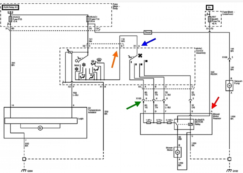
The problem with suspecting the resistor assembly is it is fed from two different 12-volt supplies. One is only for the highest speed and one is for all the others. If the fan stops working on all speeds at the same time, we have to look for what both circuits have in common.
I have a suspicion the 12 volts you found feeding the resistor is the red wire, (red arrow in my diagram). That circuit doesn't go anywhere until the highest speed is switched on, then current flows through the relay directly to the fan motor. That relay is turned on by the speed switch, just like it feeds the resistors for the lower speeds.
It's important to understand when taking voltages readings in this type of circuit, they are only valid when taken with everything plugged in and connected. There are times it is necessary to unplug things, but we need to know what to expect for voltage readings then. What can be helpful is to use an old-style test light with an incandescent bulb instead of a digital voltmeter. Test lights require current flow to give their indications. Voltmeters can falsely show a voltage in a circuit that is actually dead.
Since you already have gained access to the resistor, lets start there. Verify it's that red wire where you found 12 volts. If it is, that one can be disregarded. It's the three by the green arrow we're interested in. Switch the speed switch to any of the lower three speeds. As long as that three-wire connector, X100, is plugged in, you should find some voltage on all three wires. They're yellow, tan, and light blue wires. The voltage comes in on the wire that's switched on, and feeds through different parts of the resistor, then shows up on the other two wires. We don't care if the voltages are a little different, just whether they're there or not. If you do find voltage there, you should have it on one motor wire too. If it's there, the motor has to have a bad ground connection. That isn't likely because you said there is no voltage to the motor.
Given that observation, I'm guessing the voltage you did find was on that red wire. We need to have it on the white wire feeding the speed switch. Going back to the three wires by my green arrow, if you do not have voltage there when any of the three lower speeds are switched on, look for that white wire on the speed switch first. Leave it plugged in, then back-probe into the back of the terminal if possible, or right on the switch's terminal. If you have voltage there, suspect burned switch contacts. I'm betting by this time you're going to find a badly overheated connector terminal on one end of that white wire.
If you do find a burned terminal, the only proper repair is to replace the terminal, the wire, and the switch. Either an overheated switch or terminal will create heat that migrates into the other part, degrading the contact or strength of the terminal. The part not replaced will begin to generate heat and cause a repeat failure. The excessive heat will also migrate into the wire and cause it to become stiff. Solder won't adhere to that, and crimp-type terminals won't make a good connection. Usually about four inches of wire must be cut off, then a new section of the same gauge spliced in. For terminals, you might find what you need in a pick-your-own parts salvage yard, otherwise, I cut out any melted section of a connector body, plug it in that way, then I use a universal crimp-type terminal on the new piece of wire and plug that in separately. For the new piece of wire, solder the splice, then seal it with heat-shrink tubing. Don't use electrical tape as it will unravel into a gooey mess on a hot day. I also solder the crimped-on terminal for best connection.
Let me know how far this gets you.
Jan 14, 2025 at 4:55 PM