Alternator Overcharging

Tiny
CRAWFORDQUARTERS
  • MEMBER
  • 2001 DODGE DAKOTA
  • 4.7L
  • V8
  • 2WD
  • AUTOMATIC
  • 180,000 MILES
I have read many strings on this issue but no real solutions. My truck out of the blue started overcharging intermittently. The battery gauge goes all the way down to not charging and the check gauges light comes on. I tested with my digital meter and when this happens the alternator is actually charging at 18 volts. And the engine will not idle.

Here is what I have done so far: New alternator, new battery, new cables, and it worked correctly for about a week then the problem came back. Checked all the ground connections, even used a rubber mallet to tap on things to see if I have a loose connection. I cannot make it repeat the problem or stop the problem when it is doing it. And sometimes I start it up and it works fine for a while and sometimes I start it up and the problem is there. I have read the PCM, which has the voltage regulator in it, rarely if ever is the problem because of the built in safeguards so I really do not want to start replacing that if I do not have to.

What am I missing and is there anything else I should be looking for? This thing is driving me crazy. And why do these Dodges have these issues that no one can figure out? Thanks for any help you guys can give me here.
Wednesday, February 6th, 2019 AT 4:14 PM

13 Replies

Tiny
ASEMASTER6371
  • MECHANIC
  • 52,797 POSTS
Good evening,

The charge rate is too high and that will fail the battery.

The PCM turns the regulator on and off. The regulator is in the alternator.

There is a load detector in the PCM that controls the charge rate based on load.

Roy
Was this
answer
helpful?
Yes
No
-1
Wednesday, February 6th, 2019 AT 4:47 PM
Tiny
CARADIODOC
  • MECHANIC
  • 33,754 POSTS
Actually, they have very little charging system problems compared to other brands, and most of them are easy to diagnose. First, be aware the alternator can not cause an over-charge condition unless one of the brush terminals is grounded. That can only happen when assembling the unit. Beyond that, it just does what it is told to do by the voltage regulator. You are correct that the regulator circuit in the Engine Computer is very reliable, but they do fail on occasion. There's a better suspect though for this group of symptoms. That would be the wire going to the computer where it senses system voltage.

The "Volts" gauge in the instrument cluster doesn't actually measure system voltage as it did in the past. All of the gauges are run by the cluster's computer circuitry, and that gets its information over the data buss from the Engine Computer. If the Engine Computer thinks it is seeing 0 volts for system voltage, that is what it is going to tell the instrument cluster. At the same time, it is going to try to raise system voltage by running the alternator harder. Even though the alternator's output voltage has reached 18 volts, it is apparent the computer is still seeing 0 volts.

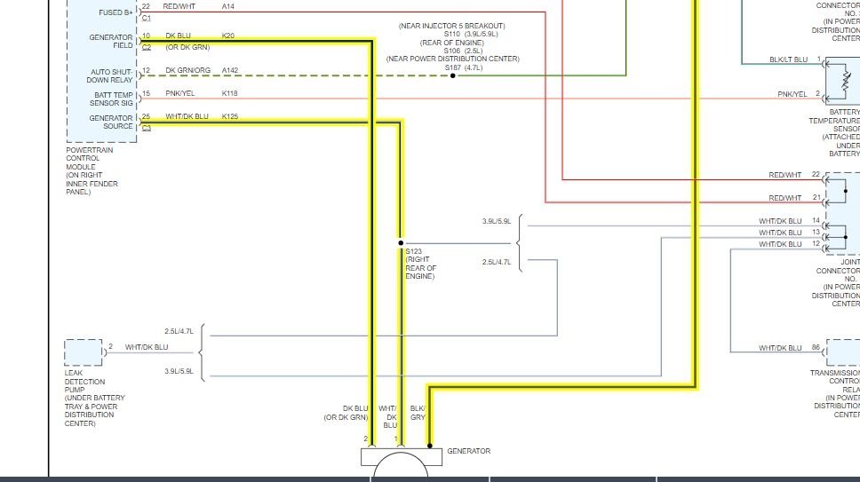
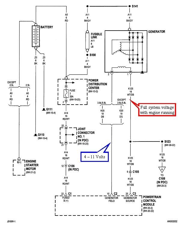
The easiest of the tests is first to measure the voltage on the two alternator field terminals. Wire colors are irrelevant at this point because both wires go into a black plastic block, so you can't know which wire goes to which terminal. That is easy enough to figure out when necessary, but not for this test.

The engine must be running when performing any voltage measurements in the charging system. Measure the voltages on the two small terminals on the back of the alternator. One is going to have full battery voltage, in this case, about 18 volts. We're interested in the other one. That one is going to be less than the first one, but not 0 volts. The lower that voltage, the greater the difference between the two, and therefore the stronger is the electromagnet. In a properly-working system, you'll typically find between 4 and 11 volts. At 4 volts the system is running nearly wide-open and charging very hard.

The voltage regulator is incapable of drawing this voltage down to less than about two volts due to all the other circuitry inside the computer. If you were to ever find 0 volts on this "control" terminal, it can only be for one of two reasons. The brushes inside the alternator are badly worn and open, or that control wire is grounded between the alternator and the computer. Open brushes will cause a failure to charge. A grounded wire will cause wide-open charging, which is what you have.

To say that a different way, if you find a real low voltage on that second field terminal, but not 0 volts, that wire can't be grounded. In that case the voltage regulator is pulling that voltage down because it thinks system voltage is too low.

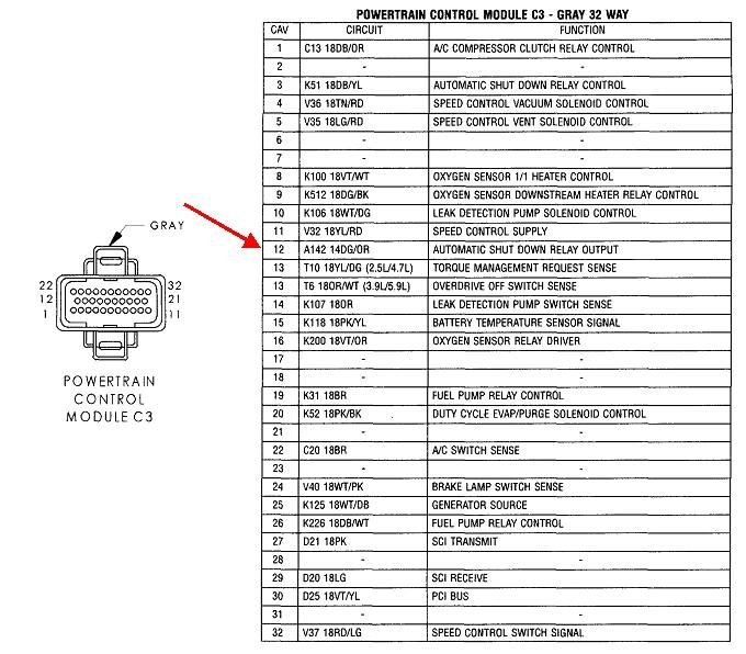
Where I would go next is to look at the system voltage sensing wire at the Engine Computer's connector and see what you have there. This gets confusing because of the terminology that doesn't seem to make sense at first. That first one second when you turn on the ignition switch, then again during engine rotation, (cranking or running), the Engine Computer turns on the automatic shutdown, (ASD) relay. That relay sends current to the ignition coils, injectors, fuel pump or pump relay, alternator field, oxygen sensor heaters, and one more wire runs right back to the computer for it to sense system voltage and to verify that ASD relay did indeed turn on. This entire circuit is called the "ASD Output" because it comes from that relay. This is terminal 12 in connector C3, shown in the third drawing.

There's usually three other 12-volt feeds to the Engine Computer. One is hot all the time to maintain fault code memory and stored data. Another one comes from the ignition switch to tell the computer to turn on. There will be other problems if either of those two circuits has a problem.
Was this
answer
helpful?
Yes
No
+4
Wednesday, February 6th, 2019 AT 6:15 PM
Tiny
CRAWFORDQUARTERS
  • MEMBER
  • 8 POSTS
Thank you Caradiodoc. I will be checking thes things later and will update you on what I find.
Was this
answer
helpful?
Yes
No
Thursday, February 7th, 2019 AT 1:34 PM
Tiny
CRAWFORDQUARTERS
  • MEMBER
  • 8 POSTS
Okay, I want to update you on my findings today Caradiodoc. Of course I started the truck and it was running and operating fine. Drove it a bit and went in the house for a while. Came back out and started it and 18v. I started by looking under the truck from front to back for any loose connections of any kind or any frayed or shorted wires or any other suspect anything. I took the time to undo every ground wire I found and cleaned with de-greaser and scuffed up paint and re-tightened them. Started the truck and still 18v. I checked the wires on the alternator and one had 18v and the other was hovering around 1v and changing rapidly as you would expect but always right around 1v. Just like you thought it would be.

I did a visual in the engine compartment and did not find anything obvious and all the sudden It just switched to working fine. Around 14.5v. I checked the dark green wire on the alternator now and it was hovering right around 8v sometimes up to 9v. And the alt was putting out at 14.5v. Just like it should be. I tried wiggling things, tapping on things and I could not make it change back to 18v. Then while I was sitting in the drivers seat thinking about it, it switched to 18v on its own again.

I wanted to tell you about some of the recent changes/repairs I made before all this started happening and get your thoughts on them. Sometime back I installed a new radio with satellite, Bluetooth and back-up camera with no issues. A couple months back the starter went out and I changed it. Right around that time I had O2 heaters throwing codes and changed them so I could pass smog tests. It was after the last two repairs the charging issue started up. Not sure if they are related or not. You mentioned the O2 heaters above So I was wondering if they could cause this problem while not throwing codes?

Lastly, I didn't get to checking the computer voltages as you suggested, ran out of time and light outside. That will be my next tests. Am I going to need to check these while it is working correctly or while at 18v or both? Thanks again Doc.
Was this
answer
helpful?
Yes
No
+1
Thursday, February 7th, 2019 AT 5:50 PM
Tiny
CARADIODOC
  • MECHANIC
  • 33,754 POSTS
Most of the connectors at the Engine Computer have covers that can be snapped off, then the wires are visible where they go into the connector body. I never approve of poking or stripping wires to take readings. Instead, use a long sewing needle and slide it in alongside the wire. Use that for the test point. I prefer to use a small jumper wire to connect the meter probe so I don't have to hang onto it. Watch what happens to the voltage when the system is working properly, and when it acts up. This is terminal 12 in connector C3. You're supposed to find the same thing that you find at the alternator feed terminal, and battery voltage. If charging voltage goes up to 18 volts and it also does that at terminal 12, the computer is not responding correctly to that high voltage. There's two possibilities for that. That terminal is not making good contact with the computer's terminal, or the computer is defective. Those terminals don't fail very often unless someone was poking around in them previously, then they can become spread too wide, especially if a meter probe got stabbed in there. The clue to a terminal problem is you can usually cause a change by wiggling on the plug or the wires.

When charging voltage goes too high, if you find less than around 13.75 volts on this wire, (typically a lot less), there is a break in that wire. Due to the interconnected circuitry inside the computer, the voltage the computer sees on its terminal will "float" to some random value. That will almost always be too low, and in response, the computer will try to raise charging voltage.

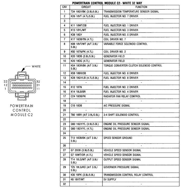
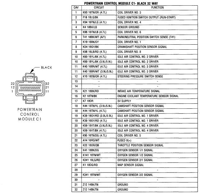
If you don't find a problem with terminal 12, check the other 12 volt supplies before you condemn the computer. I only see terminals 2 and 22 in connector C1. Normally there's a fourth terminal, but I don't see one here.

Don't forget to check the diagnostic fault codes. Do you know how to do that yourself? Cycle the ignition switch from "off" to "run" three times within five seconds without cranking the engine, leave it in "run", then watch the code numbers appear in the odometer display. You can go here to see the definitions:

https://www.2carpros.com/trouble_codes/obd2/p0400

Or we can interpret them for you.
Was this
answer
helpful?
Yes
No
+1
Thursday, February 7th, 2019 AT 6:48 PM
Tiny
CRAWFORDQUARTERS
  • MEMBER
  • 8 POSTS
I do know how to get the codes using the key and I have an ODBII code reader too. I am getting no codes at all right now or since I replaced the O2 sensors. I will be checking the voltages you talk about above tomorrow and will report back. I will say, this Dakota has been one of the most reliable vehicles I have owned up until this issue, I did wiggle all three connectors while it was working correctly and while it was at 18 volts and was not able to change the operation at all by wiggling them so I don't think at this time it is loose socket connections. So I will report my findings tomorrow.
Was this
answer
helpful?
Yes
No
Thursday, February 7th, 2019 AT 10:02 PM
Tiny
CRAWFORDQUARTERS
  • MEMBER
  • 8 POSTS
Okay, here is my report: Terminal 12 on C3 has the same 18 volts as the battery has while the engine is running and it is acting up. So I moved on to terminals 2 and 22 on C1 and they both have the same 18 volts as the battery does too. Sounding more and more like I am going to be changing out that PCM. Any suggestions on a reliable source> I have heard horror stories about going through 4 or 5 just to get a good one and I really don't want to go through that scenario if I can help it.
Was this
answer
helpful?
Yes
No
Friday, February 8th, 2019 AT 1:08 PM
Tiny
CARADIODOC
  • MECHANIC
  • 33,754 POSTS
I worked at the dealership from 1989 through 1999, and in that era there was extremely little trouble with Engine Computers. Can't say the same for '96 and newer Body Computers in the minivans. I did have a problem with the computer in my old rusty trusty '88 Grand Caravan. That one intermittently stopped reading the speed signal. The symptoms were the torque converter lockup clutch would disengage and the cruise control stopped working. A used computer cost me 25 bucks. I suspect you are also going to find a good used computer from a salvage yard will work just fine. To my knowledge, GM was the first manufacturer to trick customers with computers that had to be programmed to the vehicle by the dealer, but that didn't start until 2002 on some truck models. Chrysler has always been the industry's leading innovator with inventions that benefited the car owners, then the other manufacturers copied their designs a few years later. GM has always been the leading innovator in things that benefited GM after the sale. Of course other manufacturers eventually copy those things too, and eventually Chrysler did adopt computers that need to be programmed, but that should not apply to a 2001 model.

Speaking of Chrysler's innovations, they developed the "AC generator" for 1960 models, and copyrighted the term, "alternator". GM didn't have their version until 1964. Chrysler had the first electronic voltage regulator in 1970, the first electronic ignition system on Dodges in 1972, first lock-up torque converter in 1976, first anti-lock brakes in 1969, first air bags, and the list goes on.

Getting back to the problem at hand, there's one more thing you should consider. The voltage regulator always looks at system voltage in relation to ground, so you might want to check the voltages on the ground wires before replacing the computer. There's usually four of them; two are listed as "power grounds" and two as "signal grounds". There is always a little undesirable resistance in a wire and in its connection. When current flows through that resistance, a little voltage is "dropped" across it. It's that voltage you're going to measure, and ideally it should be 0.0000 volts. In practice, it won't be.

The power grounds are for circuits that are expected to carry high current intermittently. That includes ignition coils and injectors that are pulsed on and off, relay coils, solenoid coils, and sometimes small motors. None of those things are adversely affected by tiny changes in voltage. For example, suppose an ignition coil is fed 14.0 volts. The ground side goes through switching and monitoring circuitry inside the computer before it gets to ground, then, if there is enough resistance in the ground wire, suppose it drops 0.1 volts when current is flowing. That lowers the voltage seen across the ignition coil by 0.1 volts. That coil is not going to care in the least; it will work just fine.

Sensor circuits are a different story. MAP sensors in particular develop a very precise signal voltage based on intake manifold vacuum. It is sensitive enough that we could use it to measure engine speed because it can detect the tiny changes in vacuum each time a piston takes a gulp of air. 0.01 volt change is very meaningful to that sensor. Now, if it shared a ground circuit with the injectors and ignition coils, each time those were turned on and current flowed through them, the voltage that current causes to be dropped across the ground wire would be seen in the sensor circuits. That would cause all kinds of engine performance problems.

The voltage regulator shares the power ground circuit. It does its thing by turning the three amps of field current fully-on and fully-off around 400 times per second. Without getting into all kinds of exciting electrical theory, (unless you ask), this type of "switch mode" switching can be done easily with a very small, inexpensive transistor, and the circuit is very reliable. The same type of power supply was used in vcrs. Each time current flow is switched on, a little voltage is dropped across the ground wire. That small voltage will pulse up and down, then add the voltage drops from the ignition coil, and from the injectors, and you can see that circuit also can't be used with the circuit that monitors system voltage. That has to be part of the sensor's circuit, ... The signal ground.

In addition, there are usually two of each ground wires for redundancy in case one develops high resistance from corrosion. From taking computers apart to install "bugs" for my students to diagnose, I found the two power grounds are connected together inside the computer, so if one of those wires was cut, you will not lose some circuits. All the power circuits use both power ground wires, and all sensor circuits use both signal ground wires. Regardless, measure the voltages on all of the ground wires to be sure nothing gets overlooked.

Check terminals 4, 31, and 32 in connector C1. Now that I told you that wonderful story, I don't see a second signal ground wire. With only one wire, that would be a better suspect, but I'm pretty confident if it had enough resistance to cause a charging problem, you'd also have all kinds of running problems. Check it anyway for peace of mind.

I would expect to not find more than 0.1 or 0.2 volts on any ground wire. If you aren't sure if what you find is significant, watch if it changes when the problem comes and goes.
Was this
answer
helpful?
Yes
No
+1
Friday, February 8th, 2019 AT 6:09 PM
Tiny
CRAWFORDQUARTERS
  • MEMBER
  • 8 POSTS
Thank you again Doc. The Chrysler innovations are always interesting to me having been raised by an old Dodge mechanic so I really enjoyed that.

I will definitely be checking the grounds, though it might be a couple days. Going to visit my daughter and her family for a bit. I will definitely report back to you on my findings when I do get to check them though. Have a great weekend.
Was this
answer
helpful?
Yes
No
Friday, February 8th, 2019 AT 10:42 PM
Tiny
CRAWFORDQUARTERS
  • MEMBER
  • 8 POSTS
Wanted to get back to you doc. Didn’t get to get back out there and check the grounds but I did go ahead and get another computer. Installed it today. It is working perfectly. Things I noticed, when the old unit was working the voltage was from 14.5 volts to 14.9 volts and fluctuated a lot. With this computer installed the voltage ranges from 14.2 volts to 14.3 volts and is very stable. Not a lot of fluctuation at all. I will watch it for a few weeks but I am pretty sure it was that computer. Just wish I had gone ahead and replaced it a few months back and it would have saved me a lot of headaches.
Was this
answer
helpful?
Yes
No
Wednesday, February 13th, 2019 AT 7:21 PM
Tiny
CARADIODOC
  • MECHANIC
  • 33,754 POSTS
Dandy. I'll keep my fingers crossed.
Was this
answer
helpful?
Yes
No
+1
Thursday, February 14th, 2019 AT 4:09 PM
Tiny
CRAWFORDQUARTERS
  • MEMBER
  • 8 POSTS
Thank you so much Doc. Your information was invaluable to me and definitely directed me to the problem. So far so good.
Was this
answer
helpful?
Yes
No
Thursday, February 14th, 2019 AT 10:52 PM
Tiny
KEN L
  • MASTER CERTIFIED MECHANIC
  • 43,070 POSTS
Nice work, we are here to help, please use 2CarPros anytime.
Was this
answer
helpful?
Yes
No
Monday, February 18th, 2019 AT 10:05 AM

Please login or register to post a reply.

Sponsored links