Alternator not charging

Tiny
JEFF HERMAN
  • MEMBER
  • 2013 DODGE CHARGER
  • 5.7L
  • V8
  • 2WD
  • AUTOMATIC
  • 100,000 MILES
I removed the alternator, had it bench tested at three different outputs, 160,180 and 220 amps. Passed all 3. Battery voltage at main terminal on alternator, at this time 11.7v and 10.6v at the signal wire with ignition off. Car running only shows battery voltage or less, 11.3v. The car has a tune and pedal commander installed. There's no 120v mega fuse on top of the positive battery terminal and can't locate it in either fuse box nor can I locate the 70 amp fuse that's supposed to control voltage from the alternator. Changed the battery monitor and have the same results.
Wednesday, October 15th, 2025 AT 5:07 PM

5 Replies

Tiny
CARADIODOC
  • MECHANIC
  • 34,330 POSTS
How was that off-car testing done? There were three alternators available on that model; the 160-amp, 180-amp, and the 220-amp that you listed, but you can only have one of them. Off-engine testing is not effective as for a tiny 65-amp unit it can take over five horsepower to run it, and no bench testers have drive motors that big. Most have a one horsepower motor or less. Testing should also include the charging voltage, and a measurement for "ripple" voltage. Most on-car testers just show ripple voltage as "low" or "high" with a series of flashing LED lights. A few models can make printouts of the results. Those often show ripple voltage as an actual voltage value.

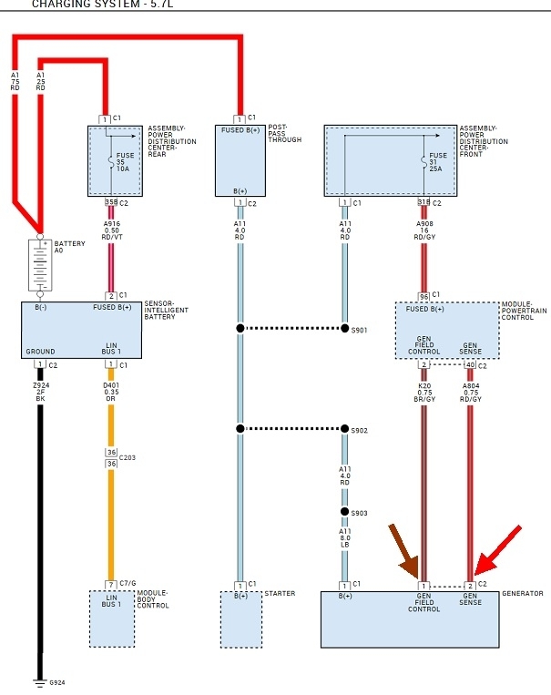
If you found 11.7 volts on the alternator's output stud with the engine not running, we know that circuit is okay. The secret to starting the diagnosis is in checking the voltages on the two smaller wires on the back of the alternator. On all older Chrysler models that had to be done with the engine running because the voltage to power the alternator's field winding came through the automatic shutdown, (ASD) relay which got turned on during engine rotation, (cranking or running). The way this diagram is drawn, it looks like that voltage is there all the time. Regardless, the engine has to be running for these voltages to be valid.

Start on the brown / gray wire. The terminology can be confusing, but normally the "generator field control" has full system voltage with the engine running, and the red / gray wire, "generator sense", will have less, but not 0.0 volts. Typically on that red / gray wire you'll find between 4 and 11 volts. The lower that voltage, the bigger the difference is in the two, and the bigger electromagnetic field is developed, meaning more output current is developed.

Let me know what you find with those two voltages.
Was this
answer
helpful?
Yes
No
+1
Thursday, October 16th, 2025 AT 11:51 AM
Tiny
CARADIODOC
  • MECHANIC
  • 34,330 POSTS
Forgot to post the diagram. The two points to test are shown with the brown and red arrows.
Was this
answer
helpful?
Yes
No
+1
Thursday, October 16th, 2025 AT 3:29 PM
Tiny
FREERIDER78
  • MEMBER
  • 8 POSTS
It turns out the previous owner crossed the two wires when he replaced the connector on the back of the alternator.
Was this
answer
helpful?
Yes
No
Tuesday, November 18th, 2025 AT 9:01 PM
Tiny
FREERIDER78
  • MEMBER
  • 8 POSTS
Can't see the reply I just sent or your response.
Was this
answer
helpful?
Yes
No
Tuesday, November 18th, 2025 AT 9:06 PM
Tiny
CARADIODOC
  • MECHANIC
  • 34,330 POSTS
Switching those two smaller wires doesn't matter. They go through a pair of brushes to the rotating field coil where it develops alternating north and south poles. Switching the wires is like walking across the room and leading off with your right foot instead of your left one. Operation is the same. The exception would be if they put some additional circuitry inside the alternator that I'm not familiar with. That IS an issue with "AC generators" on most import car models as they have their voltage regulators built in.

Chrysler was the first company to develop an electronic voltage regulator, and it was external, usually on the firewall, and easy to get to. Later, by the late 1980s / early 1990s, they built it into the Engine Computer so it could control the alternator's output based on a number of additional variables.

If switching the two smaller wires solved the no-charge problem, the previous owner either had a bad connection, or there is more to the story about what is in the alternator. I have a 2014 Ram 5.7L and a 2014 Grand Caravan. I looked up both charging system diagrams and am quite happy to find they both have the same circuit that I posted for you. If you'd like to check further, measure the voltages on those two wires with the engine running. One should have full battery voltage and the other should be between roughly 4.0 and 11.0 volts.

With those two voltages, just like they did since 1970, this system is extremely easy and quick to diagnose, so of course they had to change it in later years.
Was this
answer
helpful?
Yes
No
Wednesday, November 19th, 2025 AT 4:58 PM

Please login or register to post a reply.