Good afternoon,
The most common cause is carbon build up at the head where the air goes in. The passage gets restricted and not enough air passes the O2 sensor.
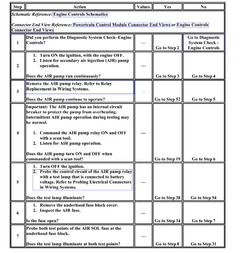
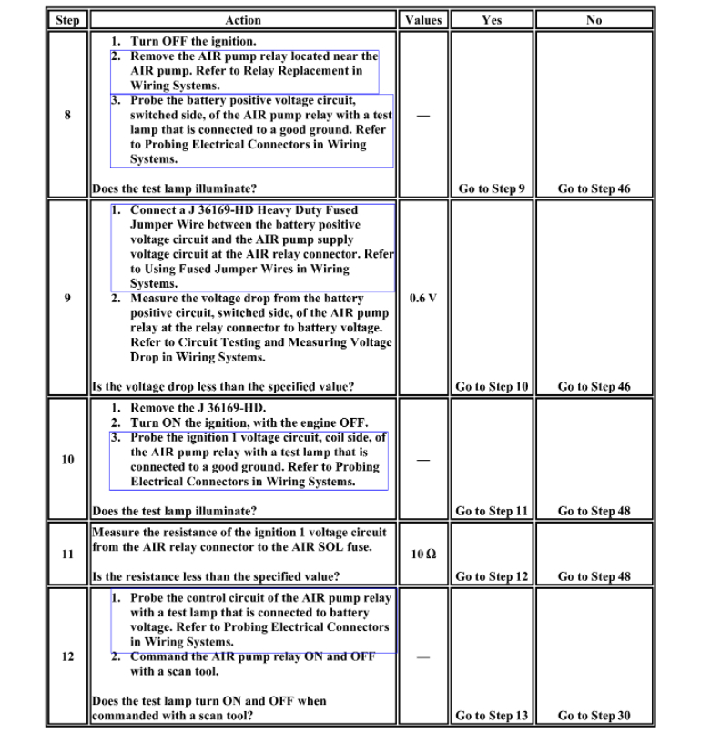
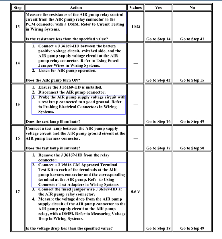
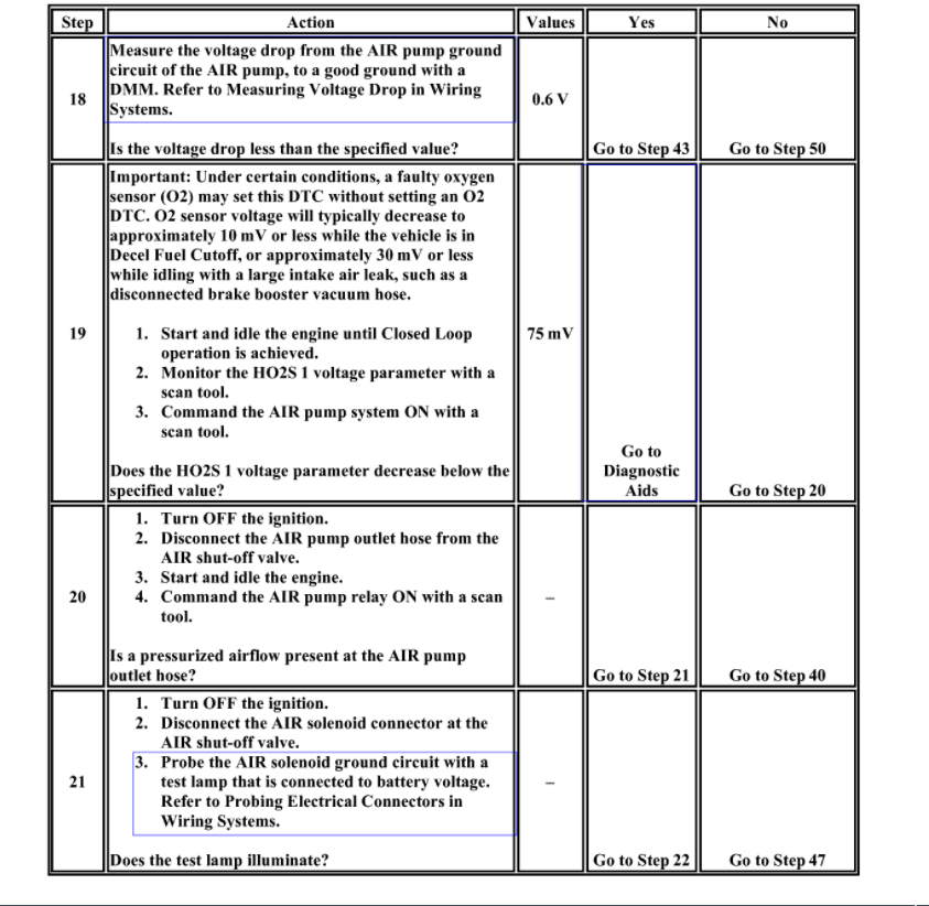
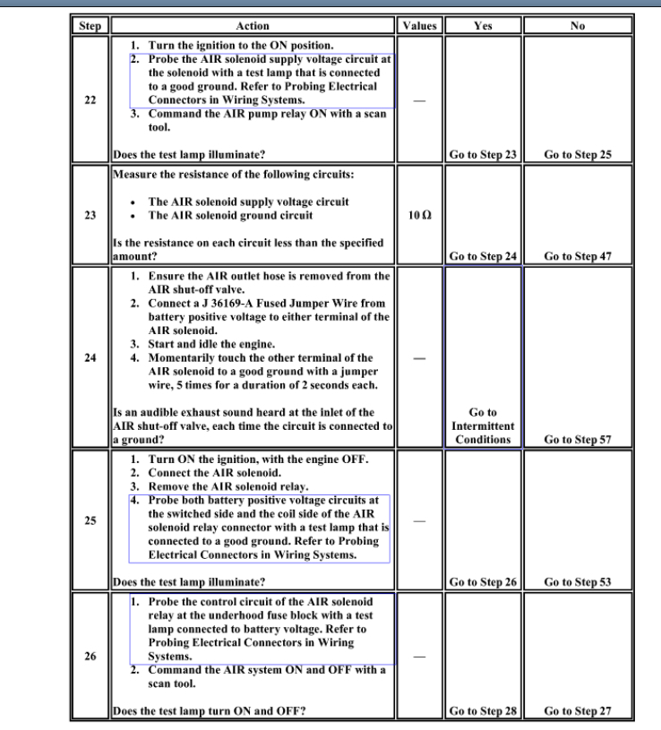
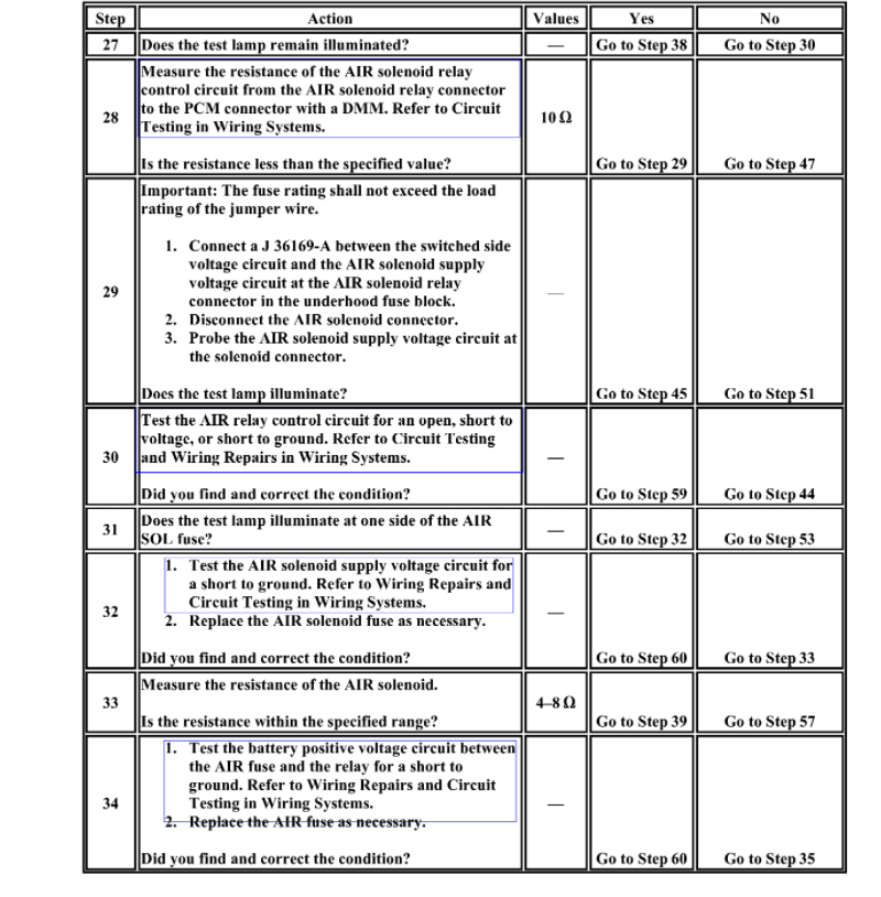
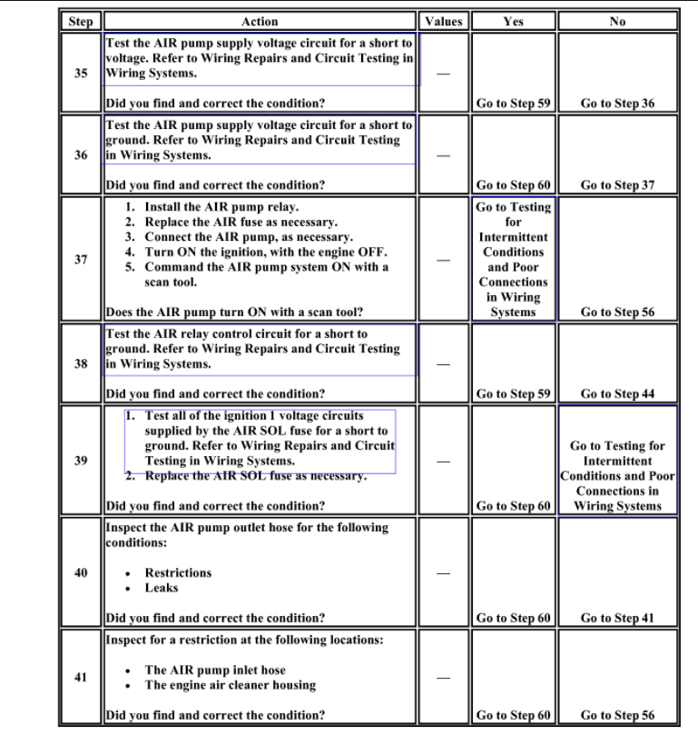
Below is the flow chart for you to follow.
Roy
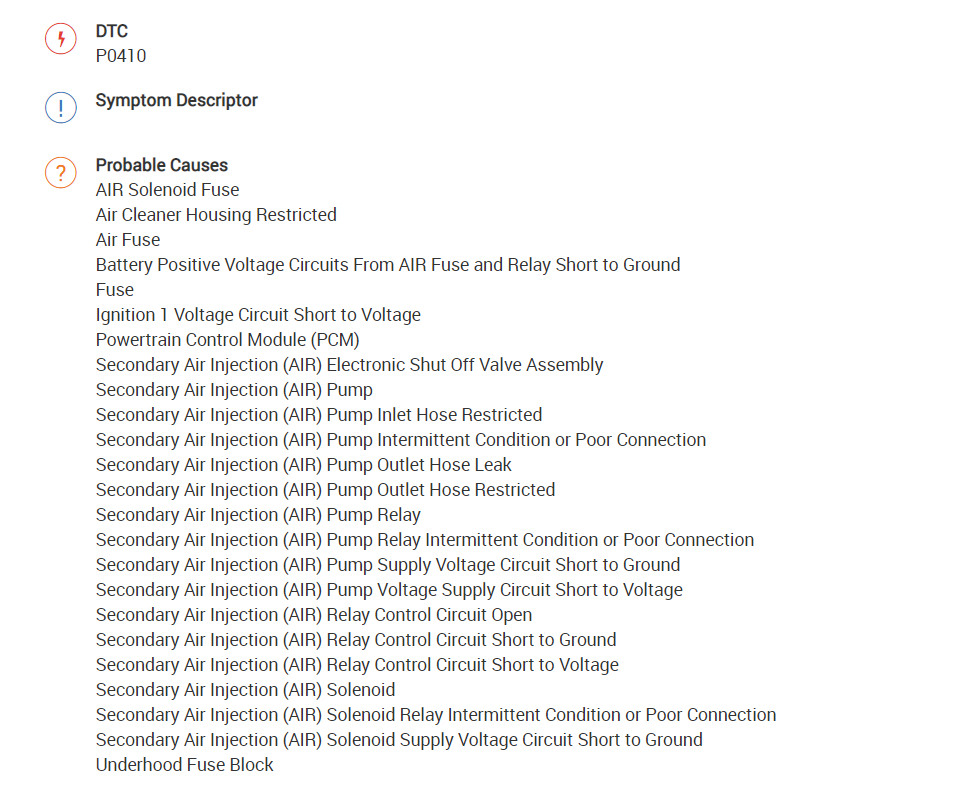
DTC P0410
Circuit Description
The secondary air injection (AIR) system is designed to reduce exhaust emissions after initial engine start-up. This occurs when coolant start up temperature and intake air temperature (IAT) are at the conditions listed below. The AIR pump will operate for less than 25 seconds. The powertrain control module (PCM) commands the AIR system ON by simultaneously supplying a ground to the AIR pump relay and the AIR solenoid relay . When commanded ON the AIR pump forces fresh air through the electronic shut-off valve and into the exhaust manifold, accelerating catalyst operation. When the AIR system is inactive, the electronic shut-off valve prevents airflow in both directions. The PCM will run the AIR diagnostic passive test only on ignition cycles when the pump is commanded ON. If this test passes, then no active test will run. If the passive test fails, or is inconclusive, the active test will run later in the ignition cycle. At that time the PCM runs a maximum of two 3 second active tests, monitoring the heated oxygen sensor (HO2S) 1 voltage, expecting a drop below 150 mV. When the PCM detects an insufficient HO2S 1 response, DTC P0410 will set.
Conditions for Running the DTC
- DTCs P0105, P0107, P0108, P0112, P0113, P0122, P0123, P0130, P0131, P0132, P0133, P0134, P0171, P0172, P0300, P0301-P0304, P0341, P0506, P0507, P0601, P0602 are not set.
- The AIR system is commanded ON for more than 20 seconds.
- The IAT is between 1-151°C (32-302°F).
- The engine coolant temperature (ECT) is between 5-114°C (41-230°F).
- The start up ECT is between 3-50°C (37-122°F).
- The battery voltage is more than 11 volts.
- The engine run time is more than 200 seconds.
- The vehicle is operating in fuel trim cells 16 or 17.
- The throttle position (TP) change is less than 5 percent.
- The manifold absolute pressure (MAP) is less than 30 kPa.
- The engine speed is more than 1,150 RPM.
Conditions for Setting the DTC
The HO2S voltage parameter does not decrease to less than 150 mV for 1 second during a 3 second active test, for 2 consecutive active tests.
Action Taken When the DTC Sets
- The control module illuminates the malfunction indicator lamp (MIL) on the second consecutive ignition cycle that the diagnostic runs and fails.
- The control module records the operating conditions at the time the diagnostic fails. The first time the diagnostic fails, the control module stores this information in the Failure Records. If the diagnostic reports a failure on the second consecutive ignition cycle, the control module records the operating conditions at the time of the failure. The control module writes the operating conditions to the Freeze Frame and updates the Failure Records.
Conditions for Clearing the MIL/DTC
- The control module turns OFF the malfunction indicator lamp (MIL) after 3 consecutive ignition cycles that the diagnostic runs and does not fail.
- A current DTC, Last Test Failed, clears when the diagnostic runs and passes.
- A history DTC clears after 40 consecutive warm-up cycles, if no failures are reported by this or any other emission related diagnostic.
- Clear the MIL and the DTC with a scan tool.
Diagnostic Aids
- An intermittent may be caused by any of the following conditions:
- Low system airflow
- Excessive exhaust system back-pressure
- Pinched, restricted, split, or damaged pipes/hoses
- Restrictions in the AIR pump inlet hose
- Pitted contacts in the AIR pump relay, AIR solenoid relay Tap on the AIR pump relay or AIR solenoid relay to attempt to duplicate an intermittent condition.
- Heat damage to the AIR outlet hose may indicate an shut-off valve failure
- Yellow tinted water in the AIR pump may indicate an shut-off valve failure
- Water or debris ingested into the AIR pump
- Observe the Freeze Frame/Failure Records to aid in conditions of setting DTC P0410.
- Thoroughly inspect any circuits that are suspected of causing the intermittent condition. Refer to Testing for Intermittent Conditions and Poor Connections See: Vehicle > Diagnostic Aids.
- If a repair is necessary, refer to Wiring Repairs or Connector Repairs See: Vehicle > Diagnostic Aids.
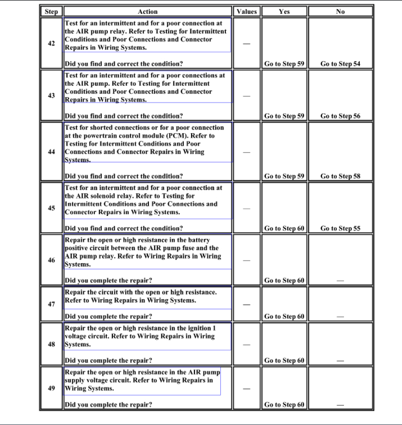
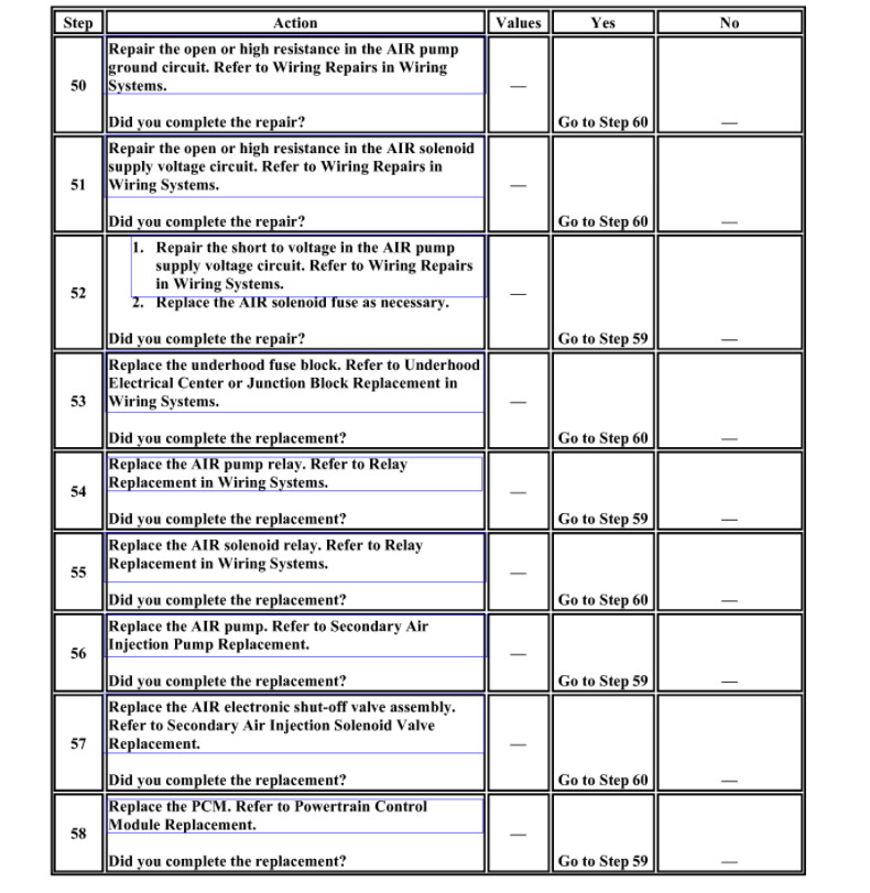
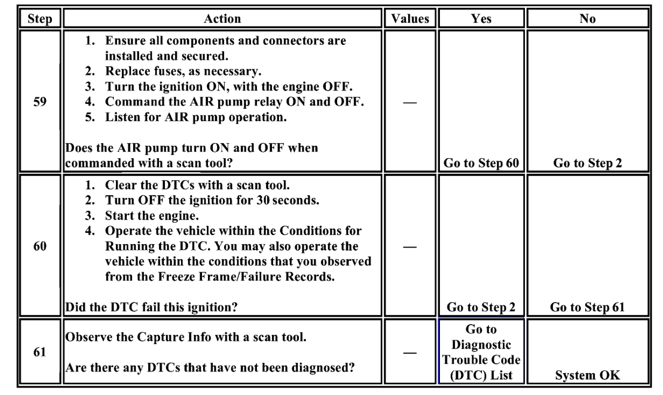
Test Description
The numbers below refer to the step numbers on the diagnostic table.
9. This step determines if excessive resistance on the supply voltage circuit between the AIR fuse and the AIR pump relay is the cause for an inoperative AIR pump. Two ohms of resistance on this circuit can prevent the AIR pump from running.
13. This step determines if excessive resistance on the AIR pump relay circuit and PCM driver is the cause for an inoperative AIR pump relay. The test lamp in series is intended to generate a electrical load on this circuit. 90 ohms of resistance on this circuit can prevent the AIR pump relay from operating.
17. This step determines if excessive resistance on the supply circuit is the cause for an inoperative AIR pump. Two ohms of resistance on this circuit can prevent the AIR pump from running.
18. This step determines if excessive resistance on the ground circuit is the cause for an inoperative AIR pump. Two ohms of resistance on this circuit can prevent the AIR pump from running.
19. This step determines if the AIR system is operating normally.
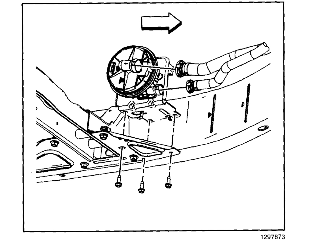
Pump
1. Raise the vehicle. Refer to Vehicle Lifting.
2. Disconnect both the air inlet and air outlet pipes from the secondary air injection (AIR) reaction pump.
3. Remove the electrical relay from the AIR pump bracket.
4. Disconnect the electrical connector from the AIR pump.
5. Remove the 3 bolts securing the AIR pump bracket to the vehicle frame.
6. Remove the AIR pump from the vehicle.
Images (Click to enlarge)
Mar 11, 2021 at 1:11 PM