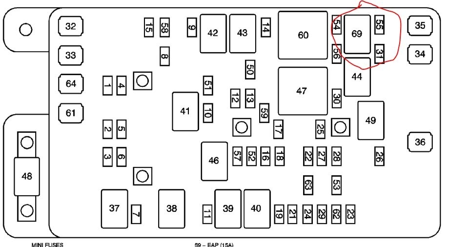
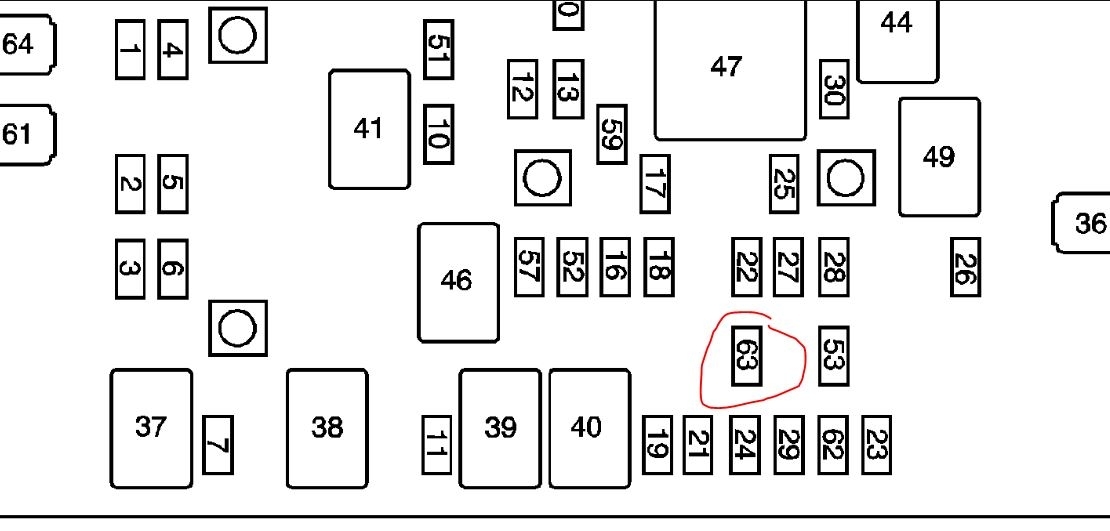
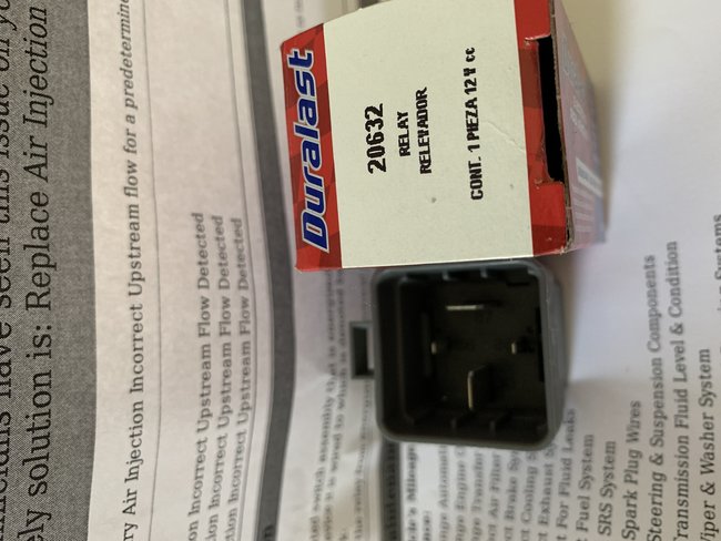
There are 2 relays. The one they gave you is on the pump. The other is in the fuse block.
You need a scan tool to check all this. You need to command the system on to verify the pump and solenoid are working.
Roy
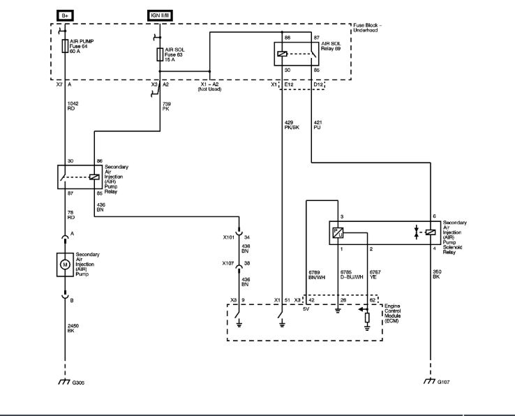
Circuit/System Description
The secondary air injection (AIR) system aids in the reduction of hydrocarbon emissions during a cold start. The system forces fresh filtered air into the exhaust stream in order to accelerate the catalyst operation. The secondary AIR injection pump provides filtered air on demand to the AIR solenoid check valve assembly. The AIR solenoid valve assembly controls the flow of air from the AIR pump to the exhaust manifold. The AIR pump relay supplies the current needed to operate the AIR pump. The AIR solenoid valve assembly has an integral check valve, pressure sensor, and solenoid valve. The pressure sensor monitors the air flow pressure from the AIR pump. The engine control module (ECM) supplies the internal pressure sensor with a 5-volt reference, a low reference, and a signal circuit. The signal circuit provides the control module with a voltage relative to internal AIR pressure changes.
The AIR diagnostic uses 3 phases to test the AIR system:
DTCs;P0411 and P2430 run during Phase 1
DTCs;P2430 and P2440 run during Phase 2
DTC;P2444 runs during Phase 3
During phase 1, both the AIR pump and the solenoid valve are activated. Normal secondary air function occurs. Expected system pressure is 8-15 kPa above BARO.
During phase 2, only the AIR pump is activated. The solenoid valve is closed. Pressure sensor performance and solenoid valve deactivation are tested. Expected system pressure is 15-22 kPa above BARO.
During phase 3, neither the AIR pump nor the solenoid valve is activated. AIR pump deactivation is tested. Expected system pressure equals BARO. In all 3 phases, testing is accomplished by comparing the measured pressure against the expected pressure. The control module can detect faults in the AIR pump, AIR solenoid, pressure sensor, and the exhaust check valve. The pressure sensor can also detect leaks and restrictions in the secondary AIR system plumbing.
Conditions for Running the DTC
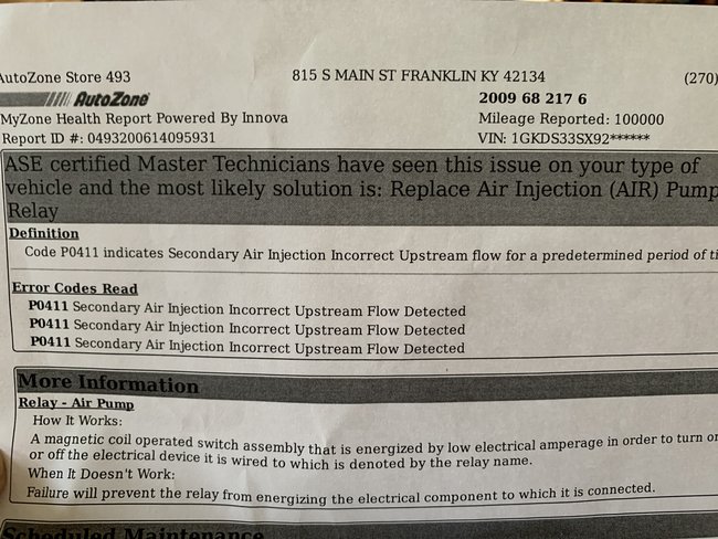
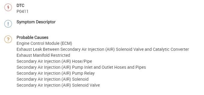
P0411
DTCs P0101, P0102, P0103, P0106, P0107, P0108, P0112, P0113, P0116, P0117, P0118, P0125, P0128, P0201-P0204, P0300, P0301-P0304, P0412, P0418, P0420, P0606, P0641, P0651, P1106, P1111, P1112, P1114, P1115, 1635, P1639, P2430, P2431, P2432, P2433, P2440, 2444 are not set.
The system voltage is between 9-18 volts.
The intake air temperature (IAT) is greater than 5°C (41°F).
The BARO parameter is more than 70 kPa.
The MAF sensor parameter is less that 33 g/s.
More than 60 minutes has elapsed since the last cold start.
The AIR system is commanded ON.
The conditions are stable for greater than 5 seconds.
DTC P0411 runs once per trip start up when the above conditions are met and the AIR pump operation is requested.
More
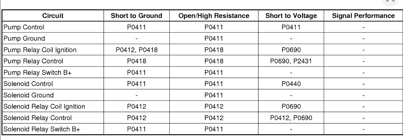
DTC P0411, P0412, P0418, P2440, or P2444
Diagnostic Instructions
Perform the Diagnostic System Check - Vehicle (See: Vehicle > Initial Inspection and Diagnostic Overview) prior to using this diagnostic procedure.
Review Strategy Based Diagnosis (See: Vehicle > Initial Inspection and Diagnostic Overview) for an overview of the diagnostic approach.
Diagnostic Procedure Instructions (See: Vehicle > Initial Inspection and Diagnostic Overview) provides an overview of each diagnostic category.
DTC Descriptors
DTC P0411
Secondary Air Injection (AIR) System Incorrect Air Flow Detected
DTC P0412
Secondary Air Injection (AIR) Solenoid Control Circuit
DTC P0418
Secondary Air Injection (AIR) Pump Control Circuit
DTC P2440
Secondary Air Injection (AIR) System Shut-Off Valve Stuck Open
DTC P2444
Secondary Air Injection (AIR) System Pump Stuck ON
Images (Click to make bigger)
Saturday, June 20th, 2020 AT 3:09 PM