Code 12 means the ignition switch was turned off recently. Code 55 means it's the "end of the message". Both of those can be ignored. Chrysler doesn't read out two identical codes so the two code 45s must have been counted wrong.
11 No crank reference signal
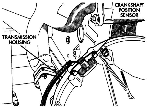
This code refers to the crankshaft position sensor circuit. About half of the time that code is caused by the sensor itself, but it's important to understand that fault codes never say to replace a part or that one is bad. In this case we have to rule out wiring and connector terminal problems in that circuit, and mechanical problems related to that sensor. Mechanical problems takes on more relevance here because the air gap for the crank sensor is critical and has special procedures for setting it. If you were to simply remove a properly-working crank sensor, then reinstall it, there's a real good chance it would not work.
There's two versions of crankshaft position sensor. You have to look at what you have now, and use the same style for replacement. One has two mounting holes in its bracket. The earlier version has only one mounting hole and it's slotted to allow for the adjustment. Original equipment sensors and some replacements have a thick paper spacer glued to the end to set the air gap. You just push it in as far as it will go, then tighten the bolt. As soon as you crank the engine, that spacer will slide off and be lost, but its job is done by then. If you need to remove and reinstall that sensor, you must use a new spacer to set the air gap again.
Some aftermarket replacement crank sensors use a thin plastic rib molded to the end of it to set the air gap. That rib can wear down a little over time, so if you need to remove and reinstall that style, you're supposed to cut the remaining part of the rib off, then use the paper spacer.
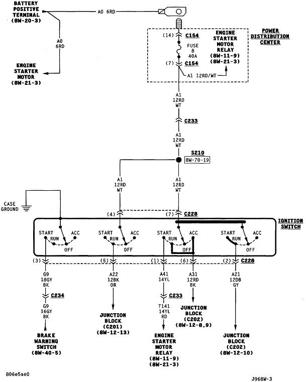
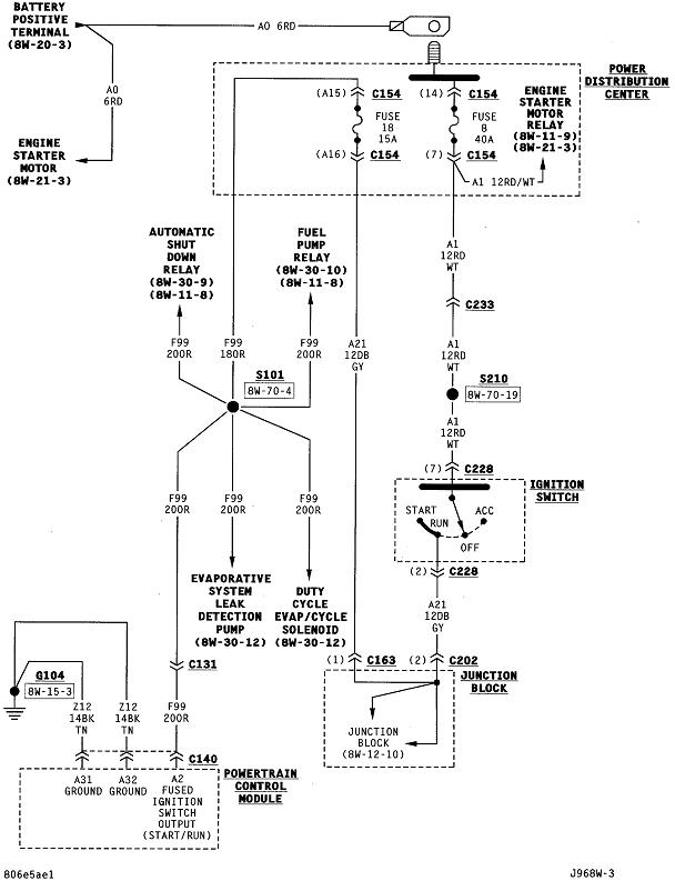
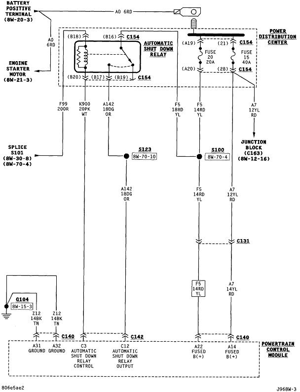
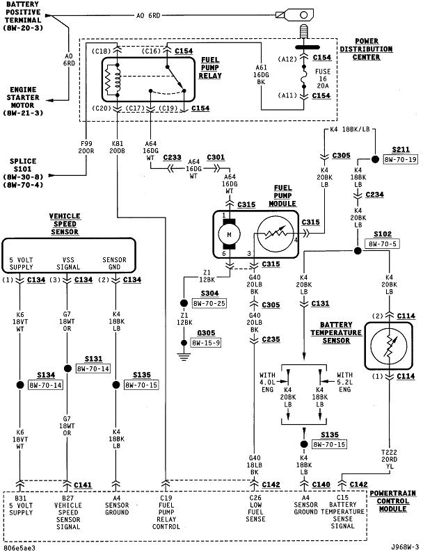
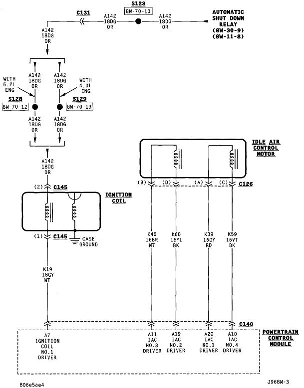
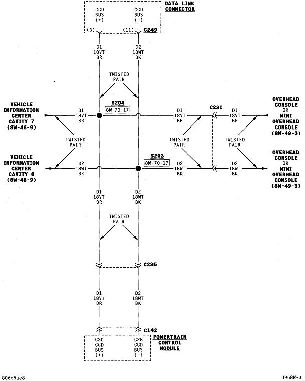
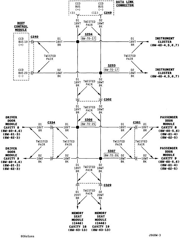
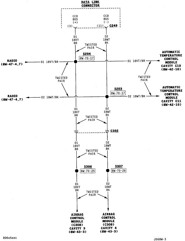
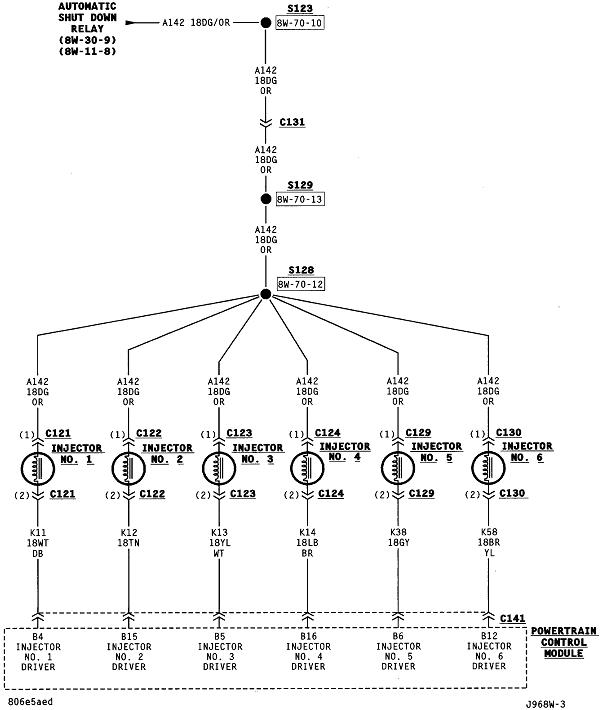
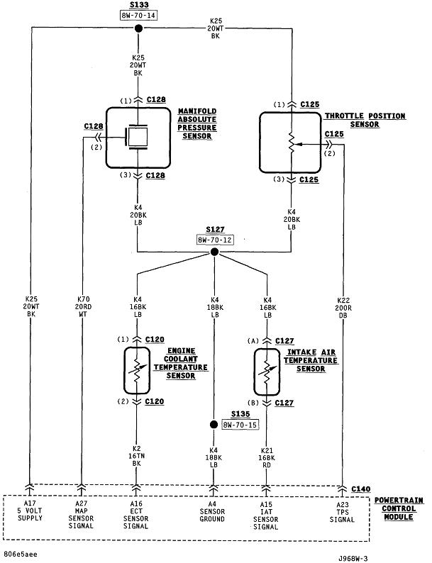
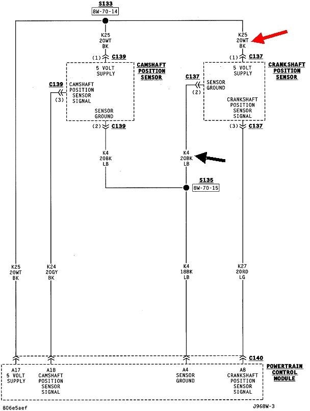
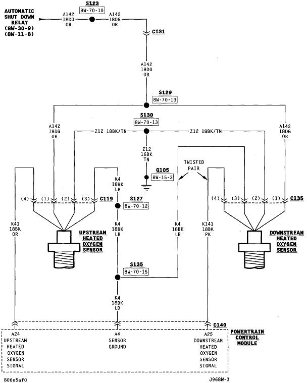
Here are all the diagrams related to the Power Train Management system. The crankshaft position sensor is in number 14. The two preliminary tests should be done by back-probing the wires through the rubber seals in the connector while the sensor is plugged in. Be aware the 5.0-volt supply and ground circuits are shared with a number of other sensors, so if one of these has a problem, you'd have fault codes for all those sensors too. What we're checking for here is if there is a break in either wire between their splices and the crank sensor connector. You should find 5.0 volts on the white / black wire, and expect to find 0.2 volts on the black / light blue wire. The only wire we haven't checked this far is the red / light green signal wire. You're much more likely to find the sensor is defective rather than that wire has a break in it.
Images (Click to enlarge)
May 8, 2019 at 1:52 PM