FRONT HUB/KNUCKLE
COMPONENTS
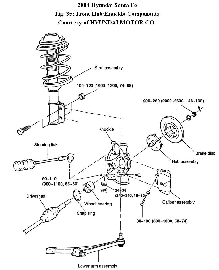
Fig. 35: Front Hub/Knuckle Components
1. Raise the vehicle and remove the front wheel.
2. Remove the wheel speed sensor from the knuckle.
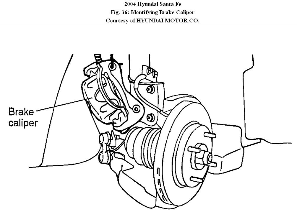
3. Remove the brake caliper and suspend it with a wire.
Fig. 36: Identifying Brake Caliper
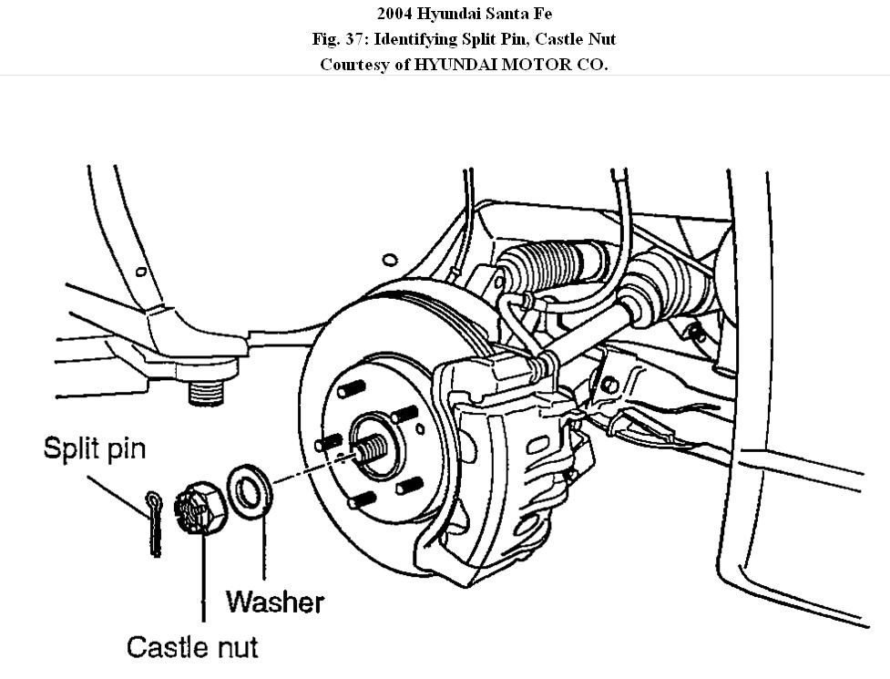
4. Remove the split pin, the castle nut and the washer from the front hub.
Fig. 37: Identifying Split Pin, Castle Nut & Washer
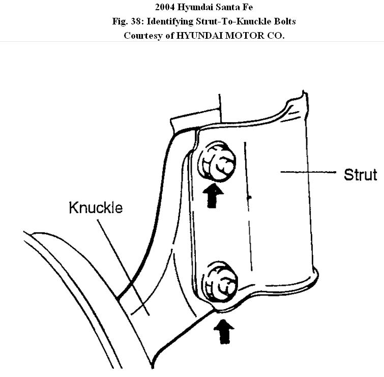
5. Remove the strut and the two bolts mounting the knuckle.
Fig. 38: Identifying Strut-To-Knuckle Bolts
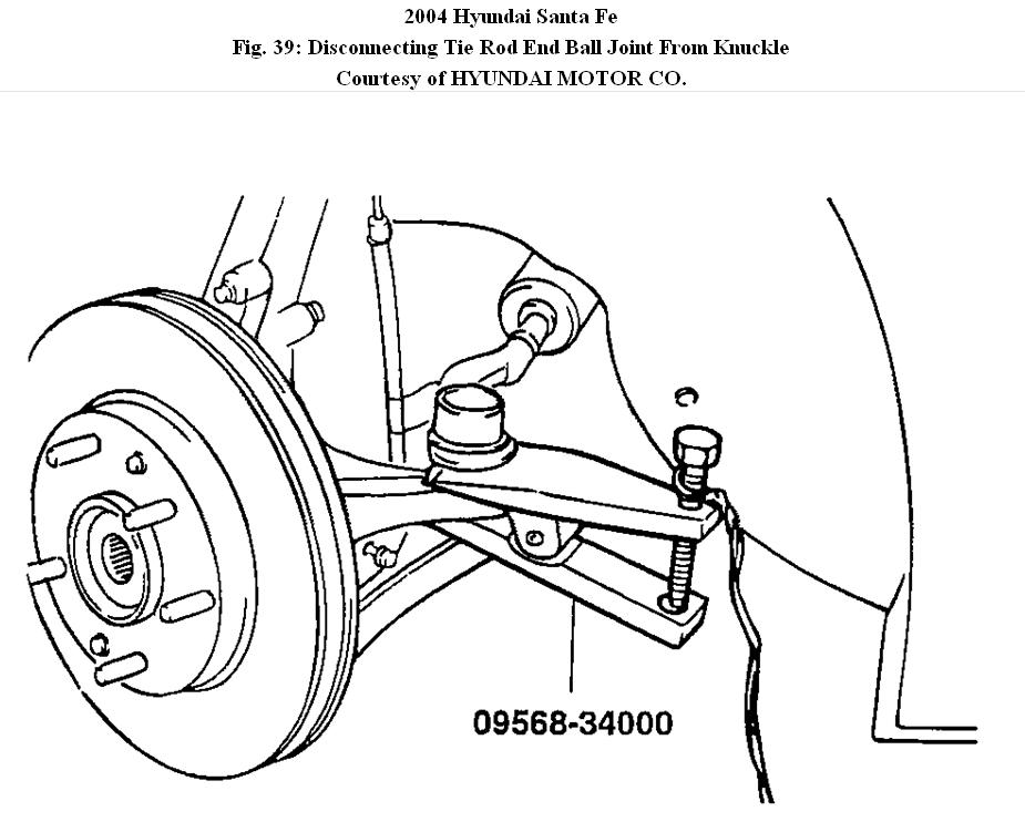
6. Disconnect the tie rod end ball joint from the knuckle using the special tool (09568-34000).
Fig. 39: Disconnecting Tie Rod End Ball Joint From Knuckle
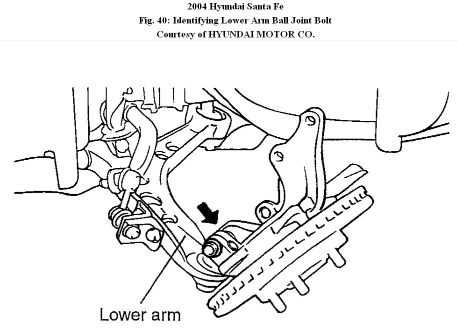
7. Remove the lower arm ball joint mounting bolt.
Fig. 40: Identifying Lower Arm Ball Joint Bolt
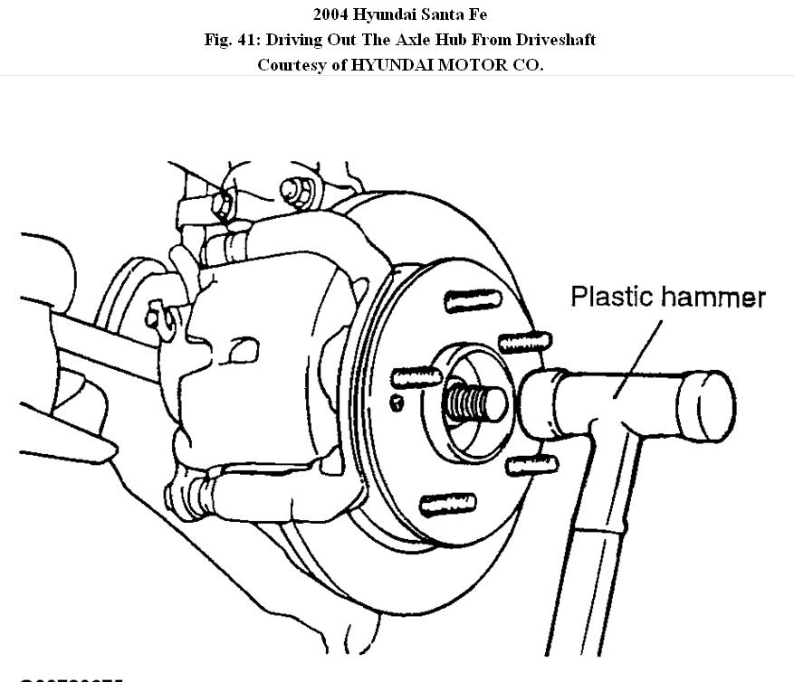
8. Using a plastic hammer, drive out the axle hub from the driveshaft.
Fig. 41: Driving Out The Axle Hub From Driveshaft
9. Remove the front axle assembly.
DISASSEMBLY
1. Remove the brake disc from the hub.
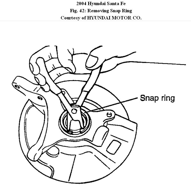
2. Remove the snap ring.
Fig. 42: Removing Snap Ring
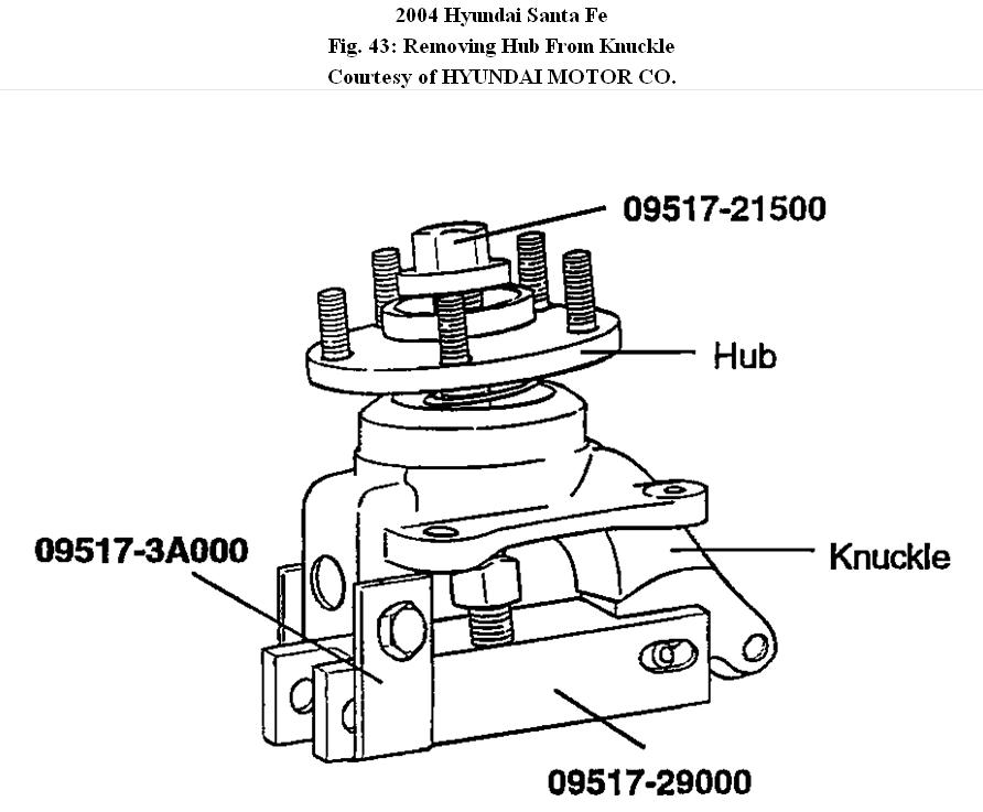
3. Remove the hub from the knuckle using the special tools (09517-21500, 09517-3A000, 09517-29000).
� Install the special tool to the hub and knuckle.
� Tighten the nut of the special tool to disconnect the hub from the knuckle.
Fig. 43: Removing Hub From Knuckle
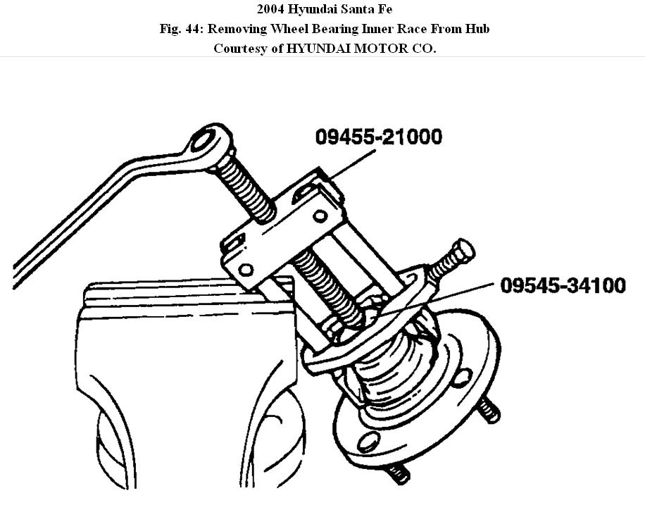
4. Using the special tools (09455-21000, 09545-34100), remove the wheel bearing inner race from the hub.
Fig. 44: Removing Wheel Bearing Inner Race From Hub
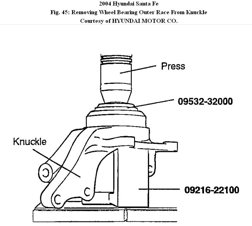
5. Using the special tools (09532-32000, 09216-22100), remove the wheel bearing outer race from the knuckle.
Fig. 45: Removing Wheel Bearing Outer Race From Knuckle
REASSEMBLY
1. Apply a thin coat of multi-purpose grease to the surface of the knuckle and bearing.
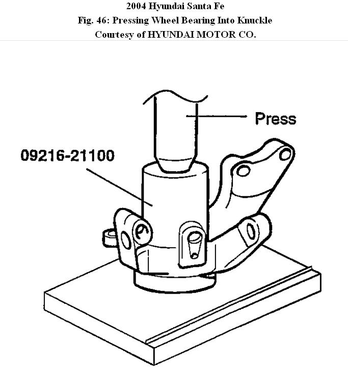
2. Using the special tool, press the bearing onto the knuckle.
Press-in load [kg(f), (lb(f))] : 4500 5000 (9921 11023)
NOTE:
� Do not press against the outer race of the wheel bearing
because that can cause damage to the bearing assembly.
� Always use a new bearing assembly.
Fig. 46: Pressing Wheel Bearing Into Knuckle
3. Install the snap ring into the groove of the knuckle.
4. Install the backing plate to the knuckle.
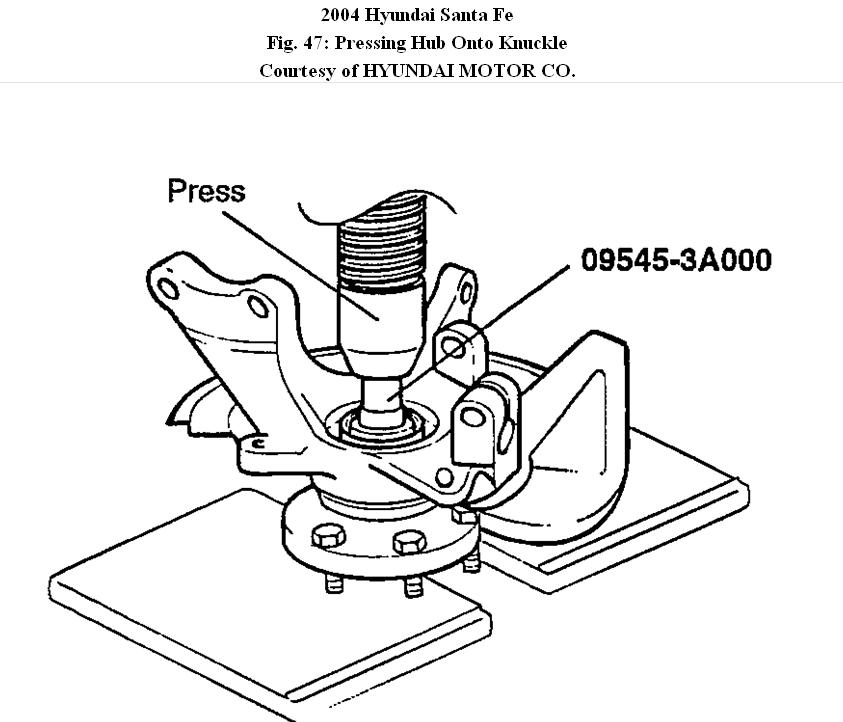
5. Press the hub onto the knuckle using a special tool.
Press-in load [kg(f), (lb(f))] : 2000 2500(4409 5512)
NOTE:
� Do not press against the outer race of the wheel bearing because this can cause damage to the bearing assembly.
Fig. 47: Pressing Hub Onto Knuckle
6. Rotate the hub several times while seating the bearing.
7. Install the disc to the hub.
4Wheel drive System Description
1. The transfer case is a full-time four-wheel drive system developed for stable driving in the worst conditions. It improves not only driving safety on a normal road but also the performance of the vehicle in a slippery road by distributing the power to both, front and rear wheels.
2. A driver may not control front or rear wheel drive directly like a four-wheel drive vehicle.
3. When the front or rear wheels slip, the viscous generates the effect of differential limitation made by viscosity torque of silicon oil inside the viscous coupling, caused by relative revolution difference among interior plates.
4. This system secures optimum drive performance and vehicle safety according to a road by transmitting viscous torque to the side there is a little slippage between front wheels and rear wheels.
5. Rear wheel power set by the above system is transmitted to the rear wheel through the hypoid gear.
Above are the description of the 4WD functions and by disconnecting the rear differentials, you would be diabling the functions and the 4WD ECU would flash to indicate trouble codes intermittently.
If vehicle is used for normal driving without any extreme conditions, disconnecting the rear differentials would not have any adverse effects.
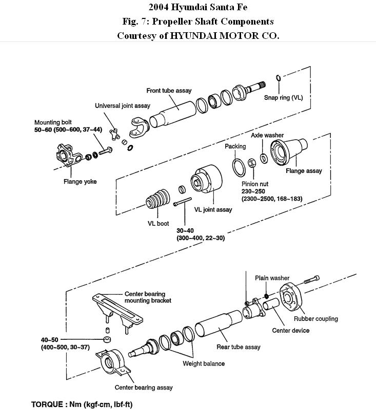
To disconnect the rear differentals, removing the propellershaft is all you need to do.
Images (Click to make bigger)
Sunday, December 12th, 2010 AT 3:26 AM