See if the following helps
DLC CIRCUIT TROUBLESHOOTING
If the ECM/PCM does not communicate with the scan tool, HDS, or I/M test equipment, do this troubleshooting procedure.
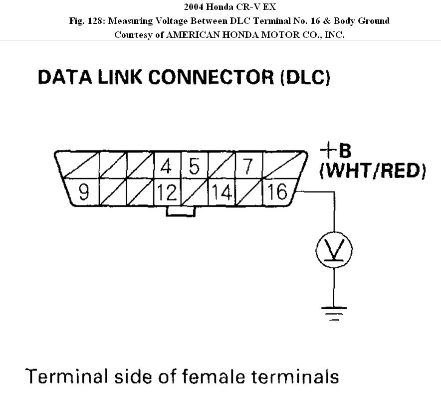
1. Measure voltage between DLC terminal No. 16 and body ground.
Fig. 128: Measuring Voltage Between DLC Terminal No. 16 & Body Ground
Is there battery voltage?
YES - Go to step 2.
NO - Repair open in the wire between DLC terminal No. 16 and the No. 9 BACK UP (10A) fuse in the under-hood fuse/relay box.
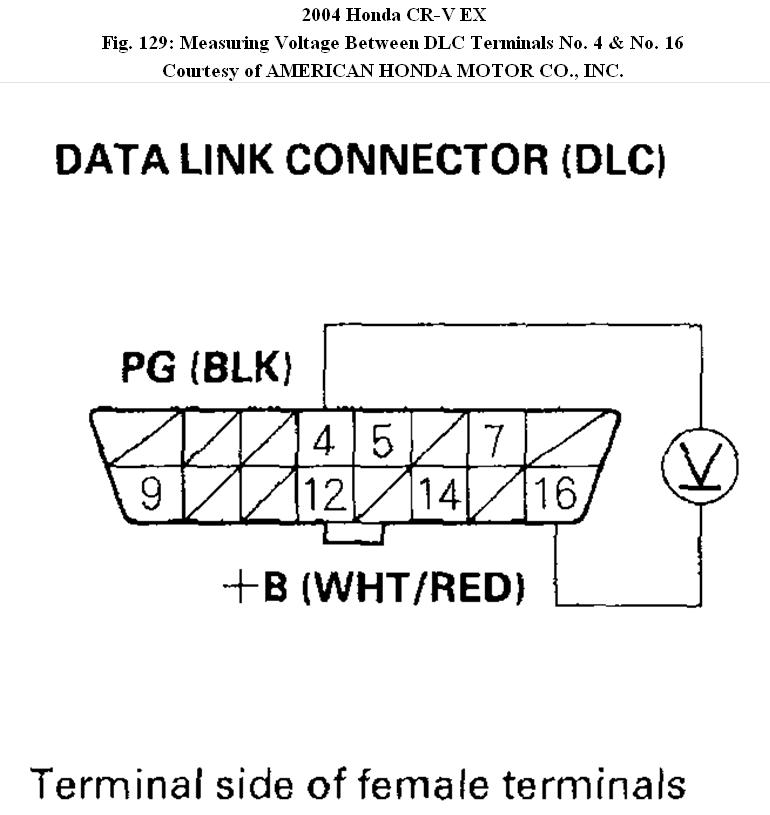
2. Measure voltage between DLC terminals No. 4 and No. 16.
Fig. 129: Measuring Voltage Between DLC Terminals No. 4 & No. 16
Is there battery voltage?
YES - Go to step 3.
NO - Repair open in the wire between DLC terminal No. 4 and body ground (G45).
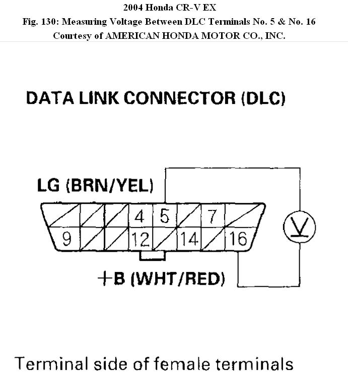
3. Measure voltage between DLC terminals No. 5 and No. 16.
Fig. 130: Measuring Voltage Between DLC Terminals No. 5 & No. 16
Is there battery voltage?
YES - Go to step 4.
NO - Repair open in the wire between DLC terminal No. 5 and the ECM/PCM (E3).
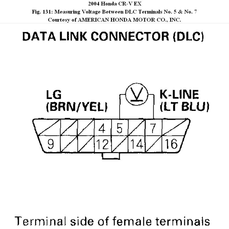
4. Turn the ignition switch ON (II).
5. Measure voltage between DLC terminals No. 5 and No. 7
Fig. 131: Measuring Voltage Between DLC Terminals No. 5 & No. 7
Is there 8.5 V or more?
YES - Go to step 10.
NO - Go to step 6.
6. Turn the ignition switch OFF.
7. Disconnect ECM/PCM connector E (31P). Make sure the scan tool or the HDS is disconnected from the DLC.
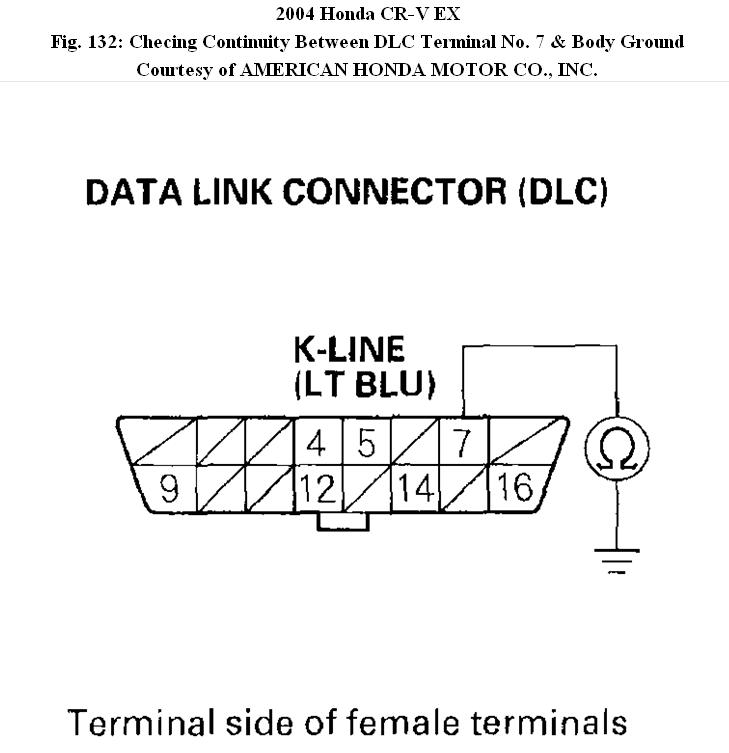
8. Check for continuity between DLC terminal No. 7 and body ground.
Fig. 132: Checing Continuity Between DLC Terminal No. 7 & Body Ground
Is there continuity?
YES - Repair short to ground in the wire between DLC terminal No. 7 and the ECM/PCM (E23). After repairing the wire, check the DTC with the scan tool or the HDS, and go to the indicated DTC's Troubleshooting.
NO - Go to step 9.
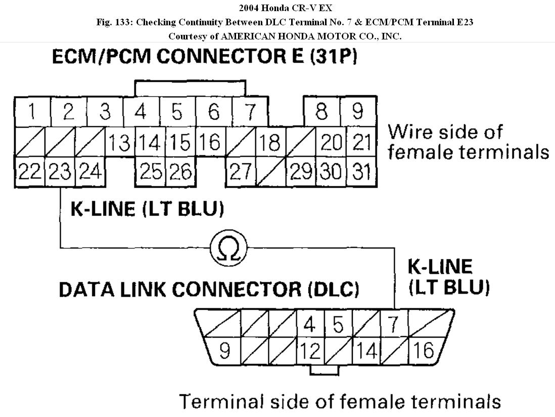
9. Check for continuity between DLC terminal No. 7 and ECM/PCM terminal E23.
Fig. 133: Checking Continuity Between DLC Terminal No. 7 & ECM/PCM Terminal E23
Is there continuity?
YES - Update the ECM/PCM if it does not have the latest software, or substitute a known-good ECM/PCM, then recheck. If the symptom/indication goes away with a known-good ECM/PCM, replace the original ECM/PCM.
NO - Repair open in the wire between DLC terminal No. 7 and the ECM/PCM (E23). After repairing the wire, check the DTC with the scan tool or the HDS, and go to the indicated DTC's Troubleshooting. Turn the ignition switch OFF.
11. Disconnect ECM/PCM connector E (31P). Make sure the scan tool or the HDS is disconnected from the DLC.
12. Turn the ignition switch ON (II).
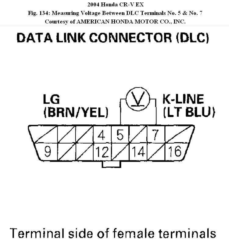
13. Measure voltage between DLC terminals No. 5 and No. 7.
Fig. 134: Measuring Voltage Between DLC Terminals No. 5 & No. 7
Is there 0V?
YES - Update the ECM/PCM if it does not have the latest software, or substitute a known-good ECM/PCM, then recheck. If the symptom/indication goes away with a known-good ECM/PCM, replace the original ECM/PCM.
NO - Repair short to power in the wire between the DLC terminal No. 7 and the ECM/PCM (E23). After repairing the wire, check the DTC with the scan tool or the HDS, and go to the indication DTC's Troubleshooting.
© 2008 Mitchell Repair Information Co., LLC.
Images (Click to enlarge)
Feb 10, 2011 at 3:46 PM