Here is how to test for a bad pcm or not
32) Check VPWR Voltage To HO2S HOTA Circuit Harness Connector
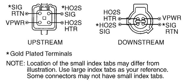
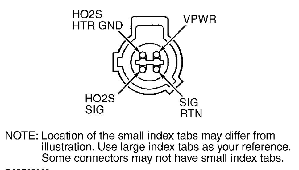
Turn ignition switch to OFF position. Disconnect suspect HO2S harness connector. Inspect wiring harness for damage and repair as necessary. Turn ignition switch to ON position. Using a DVOM, measure voltage between suspect HO2S harness connector SIG RTN and VPWR terminals. See Fig. 68 or Fig. 69. If voltage is more than 10.5 volts, go to next step. If voltage is 10.5 volts or less, on LS models go to TEST B, step 5). On all other models, check VPWR circuit fuse. Replace as necessary. If VPWR circuit fuse is okay, repair open in VPWR circuit. See WIRING DIAGRAMS article.
33) Check HO2S HOTA Circuit For Short To GND Or VPWR
Turn ignition switch to OFF position. Disconnect scan tool from DLC. Disconnect PCM connector (s). Inspect connector for loose, damaged or corroded terminals. Repair as necessary. Using a DVOM, measure resistance between PCM harness connector suspect HO2S HOTA circuit terminal and PWR GND terminal. See PCM HO2S, VPWR & GROUND TERMINAL IDENTIFICATION. See Fig. 68 or Fig. 69. Using a DVOM, measure resistance between suspect HO2S harness connector HO2S HOTA terminal and SIG RTN and VPWR terminals. If all resistance measurements are more than 10 k/ohms, go to next step. If any resistance measurement is 10 k/ohms or less, repair short in affected circuit.
34) Check HO2S HOTA Circuit For Open
Leave ignition switch turned to OFF position and HO2S disconnected. Using a DVOM, measure resistance of suspect HO2S HOTA circuit between PCM harness connector terminal and suspect HO2S harness connector terminal. See PCM HO2S, VPWR & GROUND TERMINAL IDENTIFICATION table. See Fig. 68 or Fig. 69. If resistance is 5 ohms or more, repair open circuit or excessive resistance in HOTA circuit. If resistance is less than 5 ohms, go to next step.
35) Check HO2S HOTA Resistance
you have to measure resistance not conductivity although it may show ok. And this is o2 sensor before converter.
Images (Click to make bigger)
Wednesday, March 12th, 2014 AT 12:22 PM


