Procedure
1. Turn� ignition� on.� Measure� voltage� between� ground� and� PCM� harness� connector� terminals� No.� 1, � 2, � 3, � 7, � 8� and� 9� by� backprobing.� See Fig.� 2.� Voltage� should� be�.01 .10� volts.� If� voltage� is� as� specified, � go� to� next
step.� If� voltage� is� not� as� specified, � repair� open� or� short� circuit.� See� appropriate� diagram� in� WIRING� DIAGRAMS� article.
2. Turn� ignition� off.� Disconnect� condenser� and� each� ignition� coil� harness� connector.� See Fig.� 37� and Fig.� 38�.� Turn� ignition� on.� Measure� voltage� between� each� ignition� coil� harness� connector� terminal� No.� 1� (Red
wire)� and� ground.� Also, � measure� voltage� between� condenser� harness� connector� No.� 1� (Red� wire)� and� ground.� If� battery� voltage� exists, � go� to� step 4.� If� battery� voltage� does� not� exist, � go� to� next� step.
3. Turn� ignition� off.� Check� for� open� or� short� circuit� to� ignition� coils� or� condenser.� See� appropriate� diagram� in� WIRING� DIAGRAMS� article.� Repair� as� necessary.� If� circuits� are� okay, � disconnect� condenser� and
measure� resistance� between� condenser� terminals.� Resistance� should� be� more� than� one� megohm� at� 77°F� (25°C).� Replace� condenser� if� resistance� is� not� as� specified.� If� resistance� is� as� specified, � go� to� next� step.
4. Check� continuity� of� Black� wire� between� each� ignition� coil� harness� connector� and� ground.� If� continuity� exists, � go� to� next� step.� If� continuity� does� not� exist, � repair� open� in� appropriate� Black� wire.
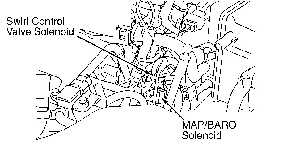
That is for code 1320 it cold be a bad coil as well. Code p1130 ccan either be the swirl control valve solenoid or the clip may be loose on it. Pic enclosed. Its 'a dealer item.
Image (Click to make bigger)
Wednesday, August 22nd, 2012 AT 8:42 PM