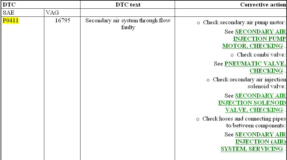
P0411 = secondary air system through flow faulty. Refer to diagram for corrective action.
Go through the procedures to check if you missed out any part.
SECONDARY AIR INJECTION (AIR) SYSTEM, SERVICING
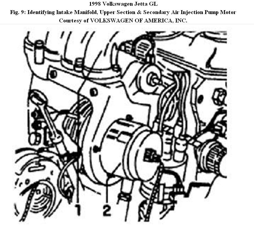
Location of Secondary Air Injection (AIR) pump motor -V101-
NOTE:
The Secondary Air Injection (AIR) system pump motor is located under the intake manifold.
1. - Intake manifold, upper section
2. - Secondary air injection pump motor
SECONDARY AIR INJECTION SYSTEM, CHECKING
Function, vehicles 06.96 and up
The Secondary air injection system injects air behind the exhaust valve for approx. 30 seconds, depending upon engine coolant temperature, load, RPM and air flow rate during the cold start (+5 °C to +40 °C engine coolant temperature).
Secondary air injection operation:
• Produces an Oxygen rich exhaust
• Causes after-burning
• Reduces the duration of the three-way catalyst heat-up phase
Activation is initiated by the Motronic Engine Control Module (ECM) -J220- via the secondary air injection system pump relay -J299- to the solenoid valve and pneumatic valve.
In addition to the engine cold start warm up phase, the secondary air injection system is checked via On Board Diagnostic (OBD)(up to an 80 °C engine coolant temperature, maximum).
If the readiness code is being created, engine coolant temperature can be above 80 °C.
SECONDARY AIR INJECTION SYSTEM COMPONENTS, REMOVING AND INSTALLING
NOTE: Complete system is checked using on board diagnostic.
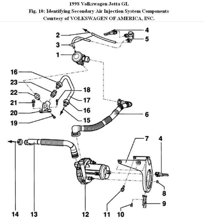
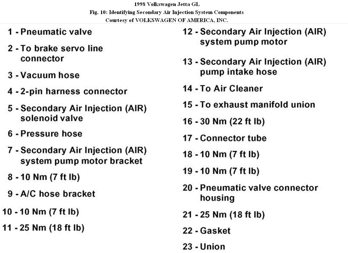
The following list pertains to Fig. 10 .
1. Pneumatic valve
• Checking, see EXHAUST MANIFOLD, FRONT PIPE AND THREE WAY CATALYTIC CONVERTER (TWC)
2. To brake servo line connector
3. Vacuum hose
4. 2-pin harness connector
5. Secondary Air Injection (AIR) solenoid valve
• Checking, see EXHAUST MANIFOLD, FRONT PIPE AND THREE WAY CATALYTIC CONVERTER (TWC)
6. Pressure hose
• Ensure it is securely seated
7. Secondary Air Injection (AIR) system pump motor bracket
8. 10 Nm (7 ft lb)
9. A/C hose bracket
10. 10 Nm (7 ft lb)
11. 25 Nm (18 ft lb)
12. Secondary Air Injection (AIR) system pump motor
• Checking, see SECONDARY AIR INJECTION PUMP MOTOR, CHECKING
13. Secondary Air Injection (AIR) pump intake hose
14. To Air Cleaner
15. To exhaust manifold union
16. 30 Nm (22 ft lb)
17. Connector tube
18. 10 Nm (7 ft lb)
19. 10 Nm (7 ft lb)
20. Pneumatic valve connector housing
21. 25 Nm (18 ft lb)
22. Gasket
• Always replace
23. Union
PNEUMATIC VALVE, CHECKING
Special tools, testers and auxiliary items
US 8026 hand vacuum pump
Test sequence
? Disconnect vacuum hose from secondary air injection solenoid valve.
? Attach US 8026 hand vacuum pump to vacuum hose.
? Disconnect pressure line from pneumatic valve.
NOTE: Do not use compressed air for the following check.
? Connect auxiliary hose to pneumatic valve and blow into it.
Pneumatic valve must be closed.
? Operate hand vacuum pump.
Valve must open and operate smoothly (without sticking).
? Replace valve if necessary.
SECONDARY AIR INJECTION PUMP MOTOR, CHECKING
Special tools, testers and auxiliary items
• VAG1598/18 test box
• VW1594 connector test kit
• VAG1527B voltage tester
Checking requirement
• Secondary Air Injection (AIR) pump relay fuse OK
Checking sequence
? Switch ignition OFF.
? Connect VAG1598/18 test box to ECM wiring harness connector.
? Disconnect pressure line from pneumatic valve.
? Switch ignition ON.
? Bridge test box sockets 01 and 06 using jumper wires from VW1594 adaptor kit.
? Connect test box terminals 49 to Ground using jumper wires from VW1594 adaptor kit.
Pump motor must run and air must exit the pressure line.
If pump motor runs, but no air exits hose:
? Check pressure line, and if necessary replace pump motor.
If pump motor does not run:
? Disconnect pump motor harness connector.
? Connect VAG1527B LED tester to disconnected connector using jumper wires from VW1594 adaptor kit.
LED tester must light up.
If tester lights up (voltage supply OK):
? Replace pump motor.
If tester does NOT light up:
? Check wiring between test box socket 49 and pump relay using wiring diagram.
? Check activation of relay and wiring to pump motor using wiring diagram.
? Reconnect 2-pin harness connector.
? Check DTC memory, then erase.
SECONDARY AIR INJECTION SOLENOID VALVE, CHECKING
Special tools, testers and auxiliary items
• VW1594 adaptor kit
• VAG1527B LED tester
• US 8026 hand vacuum pump
Checking requirement
• Vacuum hoses OK
? Disconnect vacuum hose to solenoid valve at line to brake servo. ?
Connect hand vacuum pump to vacuum hose.
? Disconnect pneumatic valve vacuum hose at valve.
? Switch ignition OFF.
? Connect VAG1598/18 test box to ECM wiring harness connector.
? Switch ignition ON.
? Connect test box terminals 01 and 06 using jumper wires from VW1594 adaptor kit.
? Operate hand vacuum pump.
Vacuum must build up (valve closed).
If vacuum does not build up:
? Replace solenoid valve 2.
If vacuum builds up:
? Connect test box socket 50 to Ground using jumper wires from VW1594 connector test kit
Valve must open.
? Operate hand vacuum pump.
Vacuum must not build up (valve open).
If vacuum builds up:
? Disconnect 2 pin harness connector from solenoid valve.
? Connect VAG1527B LED tester to harness connector using jumper wires from VW1594 adaptor kit.
LED tester must light up.
If tester lights up (voltage supply OK):
? Replace solenoid valve.
If tester does not light up:
? Check wiring for open circuit between test box socket 50 and terminal 2 of 2-pin harness connector using wiring diagram.
Resistance: 1.5 ohms maximum
? Check wiring between central electric and solenoid valve harness connector (terminal 1) using wiring diagram.
? Connect 2-pin harness connector.
? Check DTC memory, then erase.
© 2008 Mitchell Repair Information Co., LLC.
Images (Click to enlarge)
Jan 27, 2011 at 2:16 PM