1994 Geo Tracker Unknown wiring

Tiny
ARMSTRONG92071
  • MEMBER
  • 1994 GEO TRACKER
  • 1.6L
  • 4 CYL
  • 4WD
  • AUTOMATIC
  • 150,000 MILES
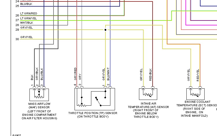
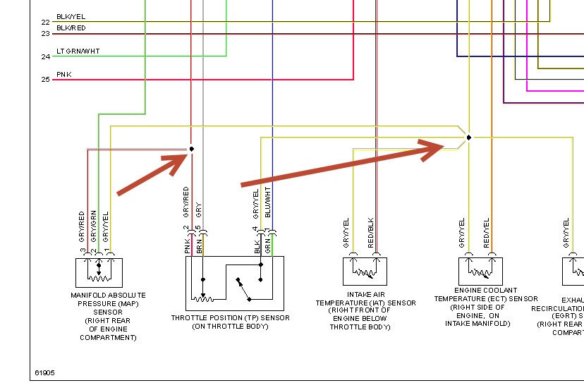
I recently changed out the TPS (throttle position switch) sensor in my 94 Tracker. While doing this, I had forgotten to identify all 6 wires and where they went. The TPS sensor only uses 4 wires. My repair manual does not specify the wiring colors or positions in the 6 wire connector. I had read something about a VSV ( some sort of switching valve?) But nothing that helps out. Since replacing the TPS, my Tracker feels like it is "grabbing" especially at low speeds but seems ok at higher speeds/rpms. I am unsure as to where to go next.
Friday, February 7th, 2014 AT 10:38 AM

11 Replies

Tiny
HMAC300
  • MECHANIC
  • 48,601 POSTS
Pic only shows 4 wires.
Was this
answer
helpful?
Yes
No
Friday, February 7th, 2014 AT 12:15 PM
Tiny
ARMSTRONG92071
  • MEMBER
  • 6 POSTS
I understand. It us because the diagram only shows the wiring for the TOS sensor and not the wiring for the connector, which I believe goes to the ECM. This is the one of the main diagrams I keep getting routed to during my searches.
Was this
answer
helpful?
Yes
No
Friday, February 7th, 2014 AT 12:23 PM
Tiny
HMAC300
  • MECHANIC
  • 48,601 POSTS
If you look at your connector it should be numbered like the one in the pic as long as you put the correct color wire into the corresponding number you should be fine.
Was this
answer
helpful?
Yes
No
Friday, February 7th, 2014 AT 12:24 PM
Tiny
ARMSTRONG92071
  • MEMBER
  • 6 POSTS
The 4 wires lead from the TPS sensor to a 6 pin connector. The 2 other wires go to some other device on the throttle body but, I do not know what it is. When I replaced the TOS, I removed the 2 other wires from the 6 pin connector/harness and forgot to mark them or write down the order they were connected. I reconnected them after I reconnected the new TPS but now my Tracker is running poorly at low RPMs. I am trying to identify what/where those 2 other wires go to and how they are supposed to connect to the 6 pin connector. I could not find that information in my repair manual. It takes me to the same wiring diagram you posted and says nothing about the other two wires and associated information. I appreciate your patience.
Was this
answer
helpful?
Yes
No
Friday, February 7th, 2014 AT 12:48 PM
Tiny
HMAC300
  • MECHANIC
  • 48,601 POSTS
Ok now you asked for it. Here is apic that it may be the wires you are talking about that connect to the gry/yellow and gry/red one which leads to map sensor and the other to the air intake sensor. Or find out what color the 6 wires are and get back to me and make sure you find out if it is a California or Federal emission which in tps case shouldn't mean much anyhow. Bu ti thin those are the two you need.
Was this
answer
helpful?
Yes
No
Friday, February 7th, 2014 AT 1:09 PM
Tiny
ARMSTRONG92071
  • MEMBER
  • 6 POSTS
The 4 wires lead from the TPS sensor to a 6 pin connector. The 2 other wires go to some other device on the throttle body but, I do not know what it is. When I replaced the TOS, I removed the 2 other wires from the 6 pin connector/harness and forgot to mark them or write down the order they were connected. I reconnected them after I reconnected the new TPS but now my Tracker is running poorly at low RPMs. I am trying to identify what/where those 2 other wires go to and how they are supposed to connect to the 6 pin connector. I could not find that information in my repair manual. It takes me to the same wiring diagram you posted and says nothing about the other two wires and associated information. I appreciate your patience.

If I follow the diagram right, it shows a gray/red wire connecting the MAL sensor with the TPS? The 2 wires I see are not connected to the TPS in any fashion. If I could figure out how to insert a picture or video, I would. That might help out a bit.
Was this
answer
helpful?
Yes
No
Friday, February 7th, 2014 AT 1:44 PM
Tiny
HMAC300
  • MECHANIC
  • 48,601 POSTS
The wires are connected at a connection point we have no videos of this I suggest you take this to a local pro to get it straightened out I have no further suggestions.
Was this
answer
helpful?
Yes
No
Friday, February 7th, 2014 AT 3:48 PM
Tiny
ARMSTRONG92071
  • MEMBER
  • 6 POSTS
Thanks for trying, I appreciate it. I know it would simplify things if I were knowledgable enough to video it to better show you what it looks like. I might try it anyway, just to see what comes of it.
Take care
Was this
answer
helpful?
Yes
No
Saturday, February 8th, 2014 AT 7:04 AM
Tiny
HMAC300
  • MECHANIC
  • 48,601 POSTS
If you are going to do that make sure that you clean the wires that arenot connected with alcohol or choke cleaner or brake cleaner to get the correct colors. Put the fluid on a rag and wipe the wires.
Was this
answer
helpful?
Yes
No
Saturday, February 8th, 2014 AT 7:08 AM
Tiny
ARMSTRONG92071
  • MEMBER
  • 6 POSTS
I can clearly identify the two wires, separate from the 4 connected to the TPS, as red and yellow, but they get wrapped together (naturally, with black tape./Plastic covering) and routed through to the back. But, I think I get your meaning. I need to do something to better identify the proper wires on the video so everyone can better trace it while watching the video or pictures. Got it!
Was this
answer
helpful?
Yes
No
Saturday, February 8th, 2014 AT 7:37 AM
Tiny
MAXIMILIAM
  • ADMIN
  • 436 POSTS
There seems to be some crossed wires on the below response. I don't understand why something about ignition problems would be associated with my Geo Tracker question.

Armstrong92071
Was this
answer
helpful?
Yes
No
Monday, February 10th, 2014 AT 6:51 AM

Please login or register to post a reply.

Sponsored links