Alternator not charging battery?

1988 FORD F-150
200 MILES
Avatar
TMAJ9447
  • MEMBER
  • 78 POSTS
After hauling a trailer this situation has occurred. I have replaced alternator, senolid, battery cables, alt wires, checked inline fuses. Chased a grounding issue to the curiosity light, fixed. And replaced ECM, found two blown capacitors. Battery charges when jumped from another vehicle @ 13+ vt, and gauge in dash works fine. Checked all fuses in fuse block, all good. Please help!
Jan 17, 2012 at 4:51 AM
Advertisement
Avatar
TMAJ9447
  • MEMBER
  • 78 POSTS
Volt/ reg and altare new even after having old one tested (good). Wire harness from alt to sol. Continuity tested good, both sides of fuseable link tested good. I will see if I can get new connectors for alt. all wires replaced with ones that have good cont. and looks good but I guess it can still not make connection at alt.
Jan 17, 2012 at 6:28 AM
Avatar
FIXITMR
  • CERTIFIED EXPERT
  • 9,990 POSTS
what colors are the alt plug wires? what motor is in truck?
Jan 17, 2012 at 6:33 AM
Advertisement
Avatar
FIXITMR
  • CERTIFIED EXPERT
  • 9,990 POSTS
so it has seperate volt reg like picture in ad page? i was thinkin it was inclusive alternator?
Jan 17, 2012 at 6:41 AM
Avatar
TMAJ9447
  • MEMBER
  • 78 POSTS
Straight 6 cyl, wires are 2 large black/org, one white ( I think) all three into fuseable link then green to solenoid. Then same 2 blk/org from connector at alt to second alt connector with 3rd green wire to ampmeter in dash.
Jan 17, 2012 at 6:44 AM
Avatar
FIXITMR
  • CERTIFIED EXPERT
  • 9,990 POSTS
i'm still confused. the white/black should plug back into alternator if reg is on alternator. and there should be a yellow/white wire that accompanies 2 large blk/org wires. can you take alternator in and get it tested?
Jan 17, 2012 at 7:24 AM
Avatar
CJ MEDEVAC
  • CERTIFIED EXPERT
  • 11,004 POSTS
We want to help, things you have said sorta do not make sense

Can you send pics of stuff like your voltage reg, backside of alternator, solenoid, use a pointer and point at stuff, like a "fusible link"???

Pics are ez to post...these pertain to my '46 jeep

The medic
Jan 17, 2012 at 1:54 PM
Avatar
TMAJ9447
  • MEMBER
  • 78 POSTS
I will get some pics up later today, the alt is new, the old alt tested good at a shop. Replaced it away, the regulated is external there are 2 big blk and org wires and a yellow white I guess wires from one plug on the alt I assume it is internal component. There is another plug 3 wires that connect to the external regulator. Hope this helps, sorry for confusion will get pic later today. Thanks for your help.
Jan 17, 2012 at 8:01 PM
Avatar
TMAJ9447
  • MEMBER
  • 78 POSTS
Ok i have attached 3 pictures. solenoid, new alt, and new connector installed tonight. the wires from solenoid are one dark green, fuselink, then 3 wires (2 blk/org) and (1 yellow/white). 2 blk/org go to 3 wire internal connector at bottom of alt. the third wire (white/blk) goes from internal connection to external connection regulator mounted on back of alt. the other 2 wires at regulator connection are green/red to ampmeter and yellow/white that goes back to fuselink at solenoid. hope this is not confusing. i did start the truck after replacing internal connector, still no charge. i disconnected the green wire from solenoid, started truck, checked with voltmeter read 0.32 volts respectively. i will have new connector for the external regulator tomorrow if you think it is not making a good connection. thanks so much for you help.
Jan 18, 2012 at 3:47 AM
Avatar
CJ MEDEVAC
  • CERTIFIED EXPERT
  • 11,004 POSTS
Fixitmr got the wiring end of this going with you---he might be able to get you a diagram, if '89 shows up in mit i

I got just 2 more questions, then i'm spent

1st pic---ammeter wire--is that a fusible link near your arrow?

Back to external regulator----did you slightly bend the spades to make better contact to the connector???

With jeep cjs they use a ford module (not related to this problem!) On 2 separate occasions (years apart) i replaced the module, as the old one tested bad------after extensive testing and really going crazy with the wires for 2 days......i took the new module back...it too was bad!.............2nd time this happened, i was alert!......now my policy is test a new one before it leaves the store! (yes, they think i'm crazy).......could it be your regulator is laughing at you now????

The medic
Jan 18, 2012 at 4:21 AM
Avatar
TMAJ9447
  • MEMBER
  • 78 POSTS
ahhh.. did not have it tested before i left (will do that). the ammeter wire at end of arrow is a bullet connector did not see a fuselink in this wire. as for the spades i did not think to bend them. as you i am spent for the day. i have a new connector tomorrow, thursday i will the day to check it again, and have the alt tested if no success. thanks again will post again thursday evening.
Jan 18, 2012 at 4:53 AM
Avatar
CJ MEDEVAC
  • CERTIFIED EXPERT
  • 11,004 POSTS
Have you run continuity test throughout the wire?

It might be a good idea to disconnect the battery first.

If you can get to the very end, you can always stick a straight pin in it.

We'll be waitin' on you

The Medic
Jan 18, 2012 at 5:12 AM
Avatar
TMAJ9447
  • MEMBER
  • 78 POSTS
ok had the new alt tested and it is good. i have prelaced both connectors now and have some success, the truck charged slowly to 9.50 volts and held there. still not enough to run the truck when neg battery term is removed. i have not cont. test the wires since the new connectors, will do tonight.
Jan 19, 2012 at 12:36 AM
Avatar
CJ MEDEVAC
  • CERTIFIED EXPERT
  • 11,004 POSTS
And the deal with mr. Voltage regulator?

The "remove a cable, while running" is not a good practice! Especially w/ a computer car!

Battery test---key off--test at battery terminals with a voltmeter

Alternator test is exactly the same, except engine is running


I did not watch this completely--you determine if it is like your set-up

Http://www.youtube.com/watch?v=kjdatypqj6o

Changing my seach words may give you more hits

The medic
Jan 19, 2012 at 2:05 AM
Avatar
TMAJ9447
  • MEMBER
  • 78 POSTS
it was tested with the alt and is good. i am watching youtube link you provided trying to gain knowledge. i have replaced and tested the wires and connectors for cont. and it test good but still not getting a charge. i add a diagram of the wire harness maybe someone knows what these wires are, what the do and what voltages they should have and educate me so i can get better information to you guys. thanks much
pic 1 is diagram of the wires
pic 2 is diagram of wires in relation to alt
pic 3 is the pig tail used to bench test the alt
Jan 19, 2012 at 4:13 AM
Avatar
CJ MEDEVAC
  • CERTIFIED EXPERT
  • 11,004 POSTS
This is supposed to be a 4.9l 1988 f-150


See what you can find with this

I do not know how it looks at 2carfellers till i post it---let me know if you cannot read it well--i can safely get it to you without you blurting out your email address

The medic
Jan 19, 2012 at 4:30 AM
Avatar
TMAJ9447
  • MEMBER
  • 78 POSTS
. one person told me that the alt might not be getting voltage to excite it to start charging. is the true in this situation? should i have 12v on on of the wires going to the alt when the key is on? thx
Jan 19, 2012 at 4:37 AM
Avatar
FIXITMR
  • CERTIFIED EXPERT
  • 9,990 POSTS
does yellow white wire show 12v?
Jan 19, 2012 at 9:17 AM
Avatar
FIXITMR
  • CERTIFIED EXPERT
  • 9,990 POSTS
are we sure alt body is grounded?
Jan 19, 2012 at 9:18 AM
Avatar
TMAJ9447
  • MEMBER
  • 78 POSTS
Please advise how to test the alt body ground and yellow white wire 12v. I have a ground light and volt meter. This may sound silly, I just want to make sure I am checking it right. Thanks I will reply with results.
Jan 20, 2012 at 2:54 PM
Avatar
CJ MEDEVAC
  • CERTIFIED EXPERT
  • 11,004 POSTS
Well sir,
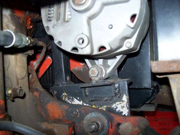
If what you are asking is how to test the actual alternator housing to insure it has a ground

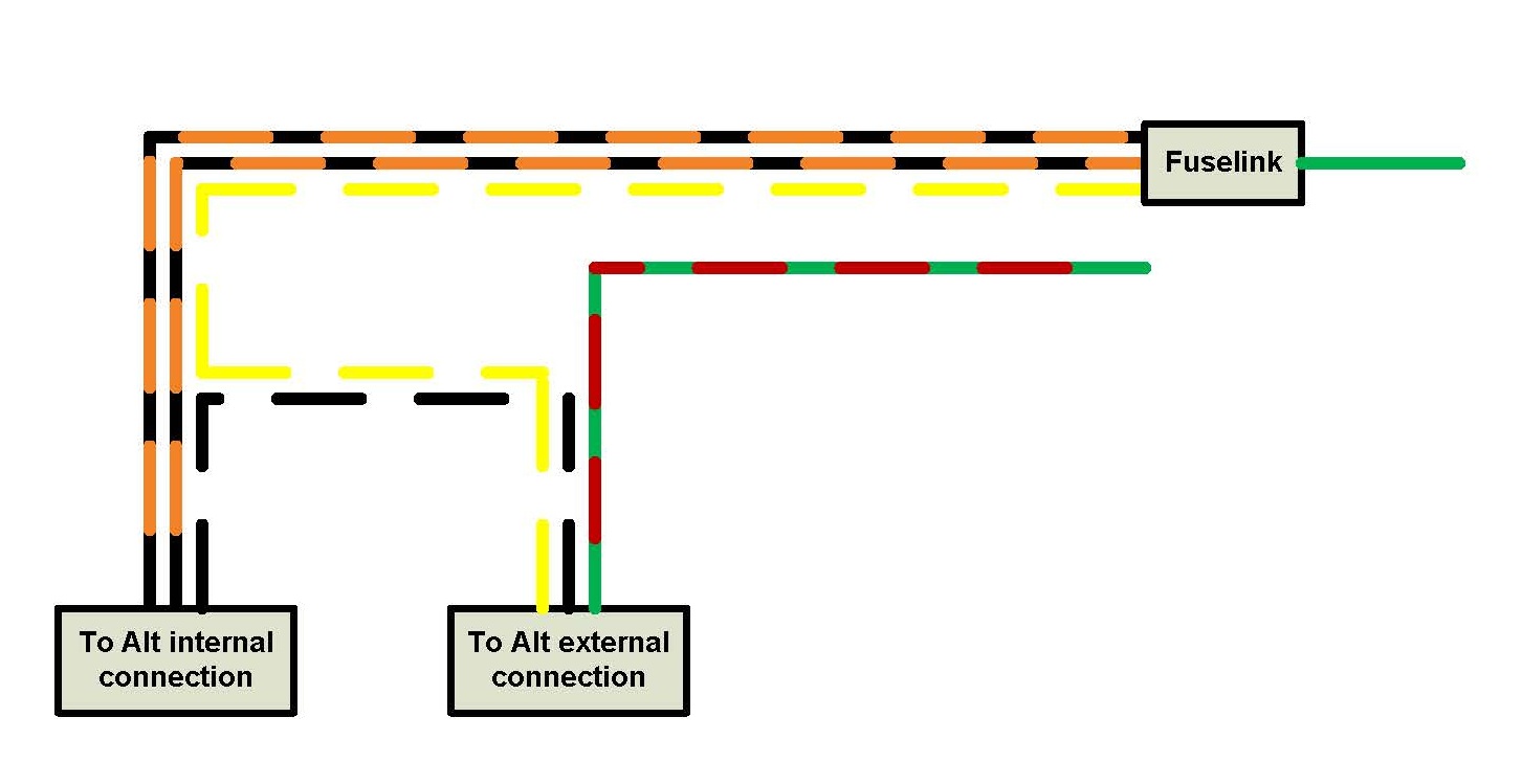
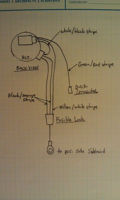
Then test the yellow/ white wire from it's connection at the alternator ("a" in the diagram) all the way back to the battery (where it finally winds up)


This can be done using "continuity"----basically this means you are sending out low voltage (like 1.5 volts) from the battery inside of the voltmeter. Down one of the leads-----then through whatever you want to test---then back up the other voltmeter lead-----thus completing the circuit


Disconnect the vehicle's battery---this will keep you from frying your meter by accident

The voltmeter is set on "ohms"--any ohm setting is fine for this application

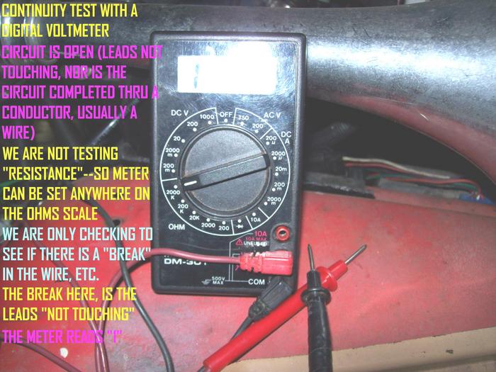
If there is no circuit (or a break in in whatever you are testing) the meter reads "1" on a digital--or "0" on a analog (meter w/ a sweeping needle)

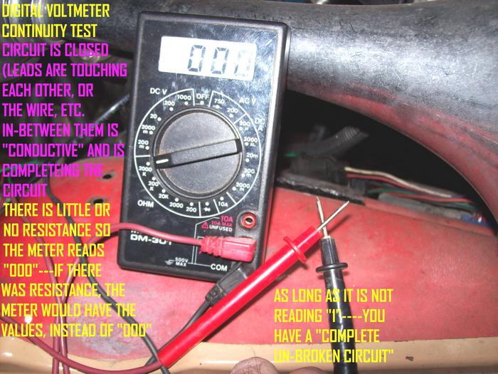
Suppose you are testing a 6 inch copper wire, placing a lead on each end of the wire "should have continuity" and a digital voltmeter will read "0" or "0.00"----on a analog voltmeter the needle will "max out".........this means there is a complete circuit or the circuit has "continuity"


Sorta another variation to this is if there is resistance in the system---you will still have "continuity" except the voltmeter with give you a measurement of the resistance, instead of "0.00"----refining the exact resistance value is the reason for the different ohm settings on the voltmeter...basically doing a "traditional continuity test" (looking for breaks) you need not worry with this.

So basically "1" means no continuity and "0.00 or a value" means the circuit got completed, and may or may not show some resistance----same goes for if the "needle has not moved"--moved partially or swept all the way across on a analog voltmeter

Some digital meters have a "beep" feature that can be used for continuity--this lets you "get on with it", without having to look at the meter face constantly.

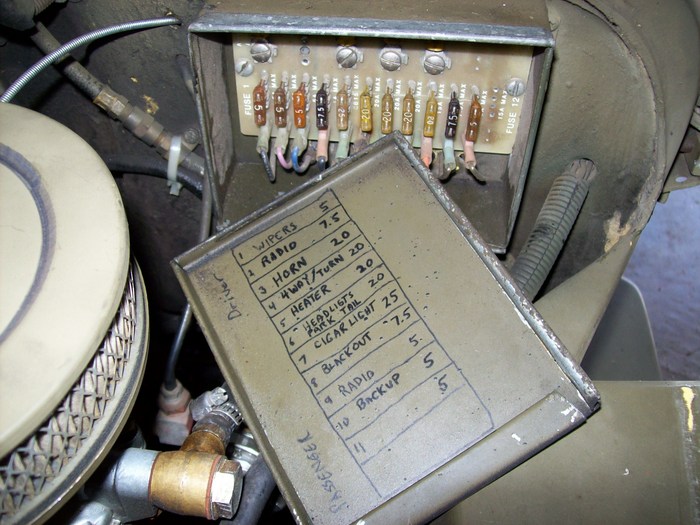
This is useful if you are crammed under your dash---checking your fuses, without removing them, just by touching the little metal test port "windows" on the fuse itself, with both leads.........just remember, disconnect the car battery 1st!


So applying this in your question/ case

Test 1) one lead on alternator case, the other on your neg battery clamp (removed from battery)

Test 2) one lead on "a" at alternator connection, the other on pos battery clamp (removed from battery)

If this ain't what you are talking about---disregard all of this---and let fixitmr attempt to aid you!

I made some pics to help out my jeep cj guys---bear with them/ i made 'em a long while back, my 1st months having ever used a computer

The medic
Jan 20, 2012 at 4:22 PM
Avatar
TMAJ9447
  • MEMBER
  • 78 POSTS
Ok yellow white wire has 12v, alt tested with ground light is grounded. Still not charging. Any more thoughts or test I can do. Thanks!
Jan 20, 2012 at 4:22 PM
Avatar
CJ MEDEVAC
  • CERTIFIED EXPERT
  • 11,004 POSTS
SURELY YOU AIN'T DONE THOSE CONTINUITY TESTS BACK TO THE BATTERY "REMOVED" BATTERY CLAMPS THAT QUICK!

THE MEDIC
Jan 20, 2012 at 4:30 PM
Avatar
TMAJ9447
  • MEMBER
  • 78 POSTS
Okay here is we're I am. When I connect the green red wire to 12 v the alt charges. Trying to trace down why the green red is not getting voltage from the ign. Yellow wire.
Jan 20, 2012 at 5:43 PM
Avatar
TMAJ9447
  • MEMBER
  • 78 POSTS
I am on a mission today, surely plus I have father in law help.
Jan 20, 2012 at 5:46 PM
Avatar
TMAJ9447
  • MEMBER
  • 78 POSTS
Found the issue instrument cluster burnt out. On way to get another will post result soon.
Jan 20, 2012 at 5:58 PM
Avatar
CADIEMAN
  • CERTIFIED EXPERT
  • 3,544 POSTS
if the dash bulb is blown.youll need to replace it for it 2 charge.you can bypass the voltage reg.with a bypass tool it plugs into the reg. wiring. it makes the alt. max charge.if it starts charging you will have to replace the voltage reg.
Jan 20, 2012 at 6:52 PM
Avatar
TMAJ9447
  • MEMBER
  • 78 POSTS
Thank for all your help. Replaced instrument cluster and it is now charging! I guess due to age the circuitry has started to separate and the circuits were touching each other. All is good the info and the diagram was a big help thank you very much. It is fixed.
Jan 20, 2012 at 8:19 PM
Avatar
CADIEMAN
  • CERTIFIED EXPERT
  • 3,544 POSTS
good for u
Jan 20, 2012 at 10:13 PM
Avatar
2CP-ARCHIVES
  • MEMBER
  • 4,540 POSTS
has new alternator but battery will still not charge
Jan 22, 2021 at 11:43 AM (Merged)
Avatar
CARADIODOC
  • CERTIFIED EXPERT
  • 34,306 POSTS
There's two generators available for your application. The older design uses an external voltage regulator with four wires in the plug. The newer design has a three-wire regulator bolted to the back of the generator. Which do you have?

If you have the newer design, check for the presence of 12 volts on one of the three plug-in wires, usually a yellow wire. If it's missing, look for a blown fuse, usually a 15 amp.

Does the "battery" warning light on the dash turn on when you turn on the ignition switch?
Jan 22, 2021 at 11:43 AM (Merged)