Code P0353, PCM Pinout, coil issue

Tiny
ANVILMONKEY
  • MEMBER
  • 2006 FORD FUSION
  • 3.0L
  • 6 CYL
  • 2WD
  • AUTOMATIC
  • 151,000 MILES
I have a P0353 DTC, replaced all coils, reset DTC and the same one came back.

I'm now testing all the wiring for coil #3 and need a pin out chart for the PCM so I can check continuity from the ground side of the connector back to the PCM connector.

Thanks in advance,
Mike
Saturday, November 14th, 2020 AT 1:32 PM

3 Replies

Tiny
JACOBANDNICKOLAS
  • MECHANIC
  • 108,328 POSTS
Hi,

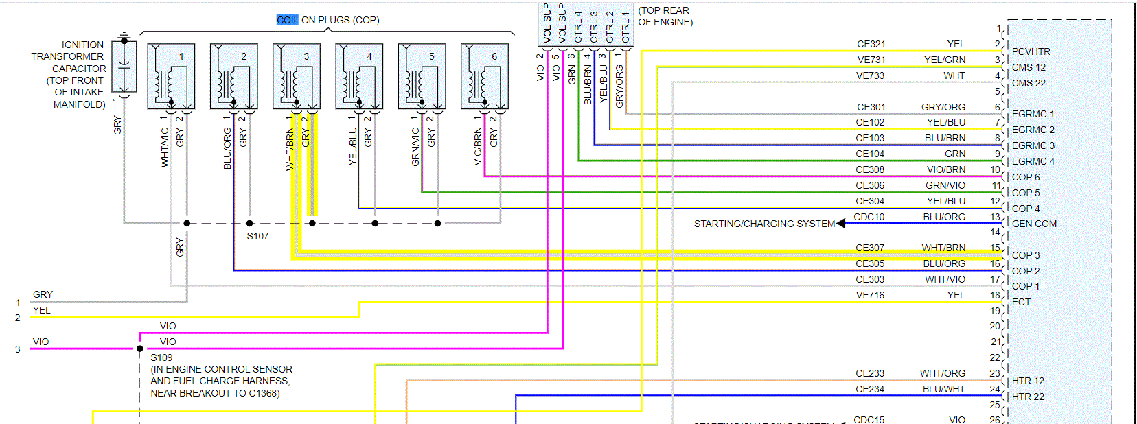
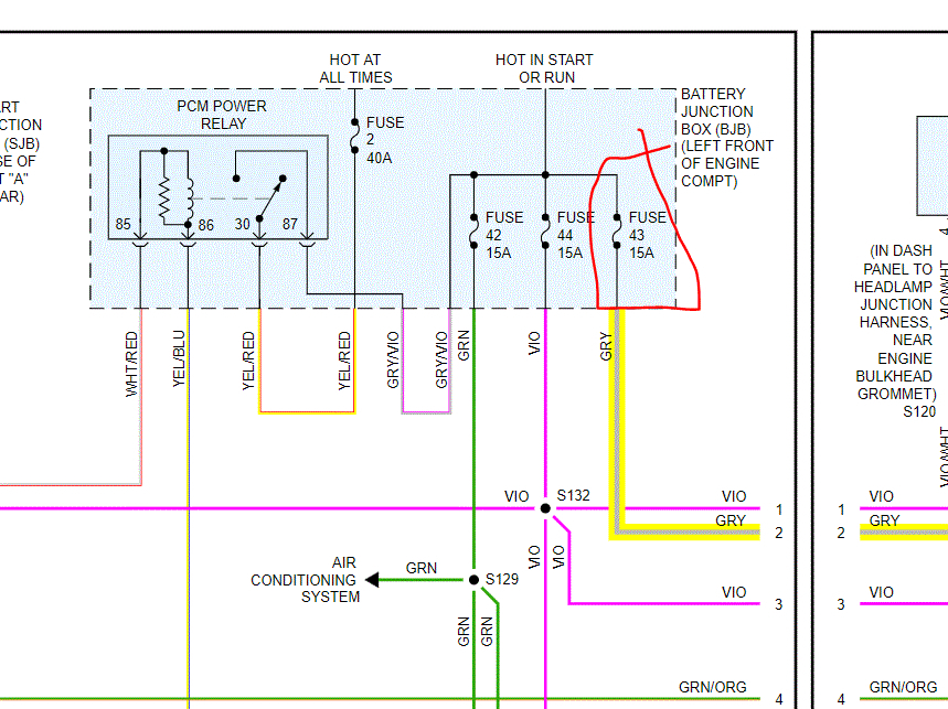
I attached and highlighted the wire to the PCM (left rear of eng compartment). Also, the gray wire goes to fuse 43 in the battery junction box. See pic 2.

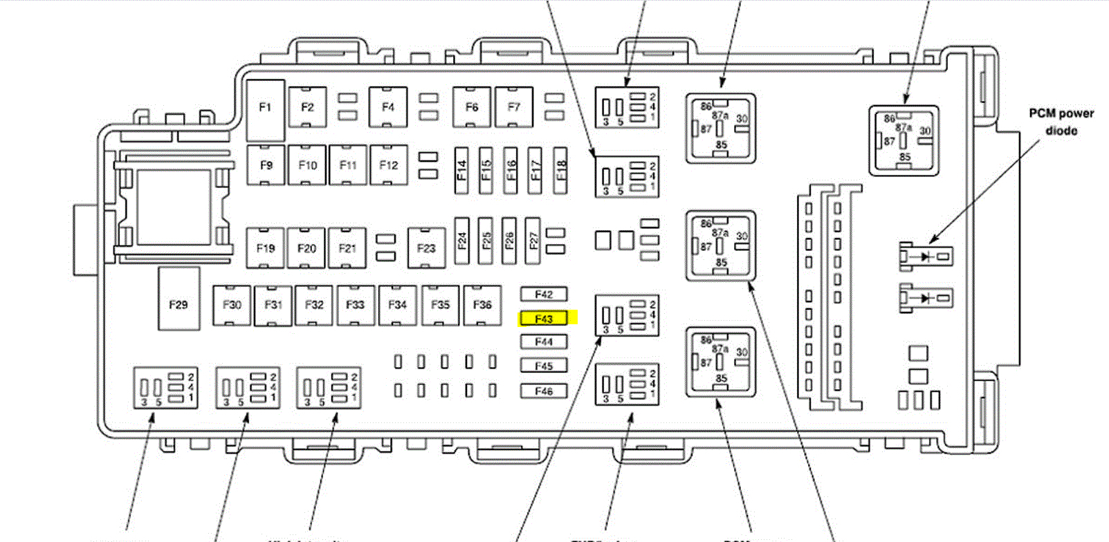
Pic 3 shows fuse 43 in box.

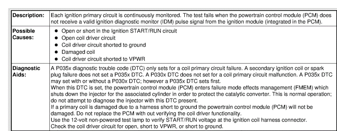
If you look at pic 4, it shows possible causes for the code. Here are the diagnostics for this type of failure.

2006 Ford Fusion V6-3.0L VIN 1
JF: Integrated Ignition Coil On Plug Coil A Through J Failure - Pinpoint Test
Vehicle Powertrain Management Computers and Control Systems Testing and Inspection Pinpoint Tests JF: Integrated Ignition Coil On Plug Coil A Through J Failure - Pinpoint Test
JF: INTEGRATED IGNITION COIL ON PLUG COIL A THROUGH J FAILURE - PINPOINT TEST
JF: Integrated Ignition Coil On Plug Coil A Through J Failure

JF: Introduction See: Computers and Control Systems > Pinpoint Tests > JF: Integrated Ignition Coil On Plug Coil A Through J Failure - Introduction

JF1 DETERMINE WHICH COIL IS NOT FIRING PROPERLY

Note:Electronic ignition engine timing is entirely controlled by the PCM. Electronic ignition timing is NOT adjustable. Do not attempt to check base timing. You will receive false readings.

- Determine which coil is not firing properly using the information from Pinpoint Test JB or a DTC and the table at the beginning of this pinpoint test.

- Record the suspect cylinder, coil and PCM pin number from the table.
Is the suspect cylinder number, coil driver and PCM pin number recorded?
Yes

- GO to JF2.

No

- REPEAT the test step to obtain the required information.

JF2 CHECK THE FUNCTIONALITY OF THE SUSPECT COIL DRIVER CIRCUIT

- Suspect coil connector disconnected.

- Connect a non-powered test lamp between the IGN START/RUN and suspect coil driver, harness side.

- Disable the fuel pump by disconnecting the inertia fuel shutoff switch.

- Observe the test lamp while cranking the engine.
Is the test lamp blinking consistently?
Yes

- GO to JF3.

No

- GO to JF4.

JF3 CHECK THE FUNCTIONALITY OF THE SUSPECT COIL

- Ignition OFF.

- Carry out a visual inspection. Closely inspect the coil case and boot for carbon tracking, cracks and torn or improperly installed boots.

- Remove the suspect COP from the spark plug.

- Connect the Air Gap spark tester 303-DO37 (D81P-6666-A) or its equivalent in series between the suspect coil tower and the spark plug wire.

- Suspect coil connector connected.

- Observe the spark tester while cranking the engine.
Is a bluish-white spark present?
Yes

- GO to Pinpoint Test Z See: Computers and Control Systems > Diagnostic Trouble Code Tests and Associated Procedures > Z: Intermittent - Introduction.

No

- INSTALL a new suspect coil. If necessary, INSTALL a new spark plug.
REFER to Ignition System.

- CLEAR the DTCs. Repeat the self-test.

JF4 CHECK THE IGNITION START/RUN VOLTAGE TO THE SUSPECT COIL

- Ignition ON, engine OFF.

- Suspect coil connector disconnected.

- Measure the voltage between:

image

Is the voltage greater than 10 V?
Yes

- GO to JF5.

No

- For Crown Victoria,

- Grand Marquis, and

- Town Car, GO to JF9.

- For All others

- REPAIR the open circuit.

- CLEAR the DTCs. REPEAT the self-test.

JF5 CHECK THE SUSPECT COIL DRIVER CIRCUIT FOR AN OPEN IN THE HARNESS

- Ignition OFF.

- PCM connector disconnected.

- Suspect coil connector disconnected.

- Measure the resistance between:

image

Is the resistance less than 5 ohms?
Yes

- GO to JF6.

No

- REPAIR the open circuit. CLEAR the DTCs. REPEAT the self-test.

JF6 CHECK THE SUSPECT COIL DRIVER CIRCUIT FOR A SHORT TO VOLTAGE IN THE HARNESS

- Ignition ON, engine OFF.

- Measure the voltage between:

image

Is the voltage less than 1 V?
Yes

- GO to JF7.

No

- REPAIR the short circuit to PWR. CLEAR the DTCs. REPEAT the self-test.

JF7 CHECK THE SUSPECT COIL DRIVER CIRCUIT FOR A SHORT TO GROUND IN THE HARNESS

- Ignition OFF.

- Measure the resistance between:

image

Is the resistance greater than 10K ohms?
Yes

- GO to JF14.

No

- REPAIR the short circuit to GND. CLEAR the DTCs. REPEAT the self-test. If the concern or DTC is still present,

- GO to JF8.

JF8 CHECK THE SUSPECT COIL FOR DAMAGE

- PCM connector connected.

- Connect the Air Gap spark tester 303-DO37 (D81P-6666-A) or its equivalent in series between the suspect coil tower and the spark plug wire.

- Locate and activate the fuel inertia switch to disable fuel pump.

- Observe the spark tester while cranking the engine.
Is a bluish-white spark present?
Yes

- If necessary, INSTALL a new spark plug. REFER to Ignition System.

- CLEAR the DTCs. REPEAT the self-test.

No

- INSTALL a new suspect coil. REFER to Ignition System.

- CLEAR the DTCs. REPEAT the self-test.

JF9 CHECK VPWR CIRCUIT CONTINUITY BETWEEN THE SUSPECT COIL AND IGNITION COILS RELAY

- Ignition OFF.

- Ignition Coils Relay connector disconnected.

- Measure the resistance between:

image

Is the resistance less than 5 ohms?
Yes

- GO to JF10.

No

- REPAIR the open circuit.

- The open is between the splice and the ignition coils relay.

- CLEAR the DTCs. REPEAT the self-test.

JF10 CHECK THE B+ AND IGN START/RUN VOLTAGE TO THE IGNITION COILS RELAY

- Ignition ON, engine OFF.

- Measure the voltage between:

image

Are the voltages greater than 10 V?
Yes

- GO to JF11.

No

- REPAIR the open circuit. CLEAR the DTCs. REPEAT the self-test.

JF11 CHECK THE IGNITION COILS RELAY CIRCUIT FOR AN OPEN IN THE HARNESS

- Measure the voltage between:

image

Is the voltage greater than 10 V?
Yes

- GO to JF12.

No

- REPAIR the open circuit. CLEAR the DTCs. REPEAT the self-test.

JF12 CHECK THE IGNITION COILS RELAY

- Carry out the ignition coils relay component test.
Is a concern present?
Yes

- INSTALL a new Ignition Coils relay. CLEAR the DTCs. REPEAT the self-test.

No

- GO to JF13.

JF13 TEST DIRECTION FOR PINPOINT TEST A

Were you directed to this pinpoint test from pinpoint test step A8?
Yes

- GO to A9 See: Computers and Control Systems > Diagnostic Trouble Code Tests and Associated Procedures > A: No Start - Pinpoint Test.

No

- GO to JF14.

JF14 CHECK FOR CORRECT PCM OPERATION

- Disconnect all the PCM connectors.

- Visually inspect for:
- pushed out pins.
- corrosion.
- Connect all the PCM connectors and make sure they seat correctly.

- Carry out the PCM self-test and verify the concern is still present.
Is the concern still present?
Yes

- INSTALL a new PCM. REFER to Section 2, Flash Electrically Erasable Programmable Read Only Memory (EEPROM) See: Computers and Control Systems > Diagnostic Trouble Code Tests and Associated Procedures > Flash Electrically Erasable Programmable Read Only Memory (EEPROM).

No

- The system is operating correctly at this time. The concern may have been caused by a loose or corroded connector.

_____________________________________

Let me know if this helps.

Take care,
Joe
Was this
answer
helpful?
Yes
No
Saturday, November 14th, 2020 AT 5:59 PM
Tiny
ANVILMONKEY
  • MEMBER
  • 2 POSTS
Thanks a lot for the images and the test procedure. By chance would you have any images that the test refers to?
Was this
answer
helpful?
Yes
No
Monday, November 16th, 2020 AT 11:58 AM
Tiny
JACOBANDNICKOLAS
  • MECHANIC
  • 108,328 POSTS
Hi,

I am going to relist the directions and the images. I felt this would make it easier to follow. Also, I'm not sure why I didn't add them originally. Sorry about that.

_________________________________

2006 Ford Fusion V6-3.0L VIN 1
JF: Integrated Ignition Coil On Plug Coil A Through J Failure - Pinpoint Test
Vehicle Powertrain Management Computers and Control Systems Testing and Inspection Pinpoint Tests JF: Integrated Ignition Coil On Plug Coil A Through J Failure - Pinpoint Test
JF: INTEGRATED IGNITION COIL ON PLUG COIL A THROUGH J FAILURE - PINPOINT TEST
JF: Integrated Ignition Coil On Plug Coil A Through J Failure

JF: Introduction See: Computers and Control Systems > Pinpoint Tests > JF: Integrated Ignition Coil On Plug Coil A Through J Failure - Introduction

JF1 DETERMINE WHICH COIL IS NOT FIRING PROPERLY

Note: Electronic ignition engine timing is entirely controlled by the PCM. Electronic ignition timing is NOT adjustable. Do not attempt to check base timing. You will receive false readings.

- Determine which coil is not firing properly using the information from Pinpoint Test JB or a DTC and the table at the beginning of this pinpoint test.

- Record the suspect cylinder, coil and PCM pin number from the table.
Is the suspect cylinder number, coil driver and PCM pin number recorded?
Yes

- GO to JF2.

No

- REPEAT the test step to obtain the required information.

JF2 CHECK THE FUNCTIONALITY OF THE SUSPECT COIL DRIVER CIRCUIT

- Suspect coil connector disconnected.

- Connect a non-powered test lamp between the IGN START/RUN and suspect coil driver, harness side.

- Disable the fuel pump by disconnecting the inertia fuel shutoff switch.

- Observe the test lamp while cranking the engine.
Is the test lamp blinking consistently?
Yes

- GO to JF3.

No

- GO to JF4.

JF3 CHECK THE FUNCTIONALITY OF THE SUSPECT COIL

- Ignition OFF.

- Carry out a visual inspection. Closely inspect the coil case and boot for carbon tracking, cracks and torn or improperly installed boots.

- Remove the suspect COP from the spark plug.

- Connect the Air Gap spark tester 303-DO37 (D81P-6666-A) or its equivalent in series between the suspect coil tower and the spark plug wire.

- Suspect coil connector connected.

- Observe the spark tester while cranking the engine.
Is a bluish-white spark present?
Yes

- GO to Pinpoint Test Z See: Computers and Control Systems > Diagnostic Trouble Code Tests and Associated Procedures > Z: Intermittent - Introduction.

No

- INSTALL a new suspect coil. If necessary, INSTALL a new spark plug.
REFER to Ignition System.

- CLEAR the DTCs. REPEAT the self-test.

JF4 CHECK THE IGNITION START/RUN VOLTAGE TO THE SUSPECT COIL

- Ignition ON, engine OFF.

- Suspect coil connector disconnected.

- Measure the voltage between:

pic 1

Is the voltage greater than 10 V?
Yes

- GO to JF5.

No

- For Crown Victoria,

- Grand Marquis, and

- Town Car, GO to JF9.

- For All others

- REPAIR the open circuit.

- CLEAR the DTCs. REPEAT the self-test.

JF5 CHECK THE SUSPECT COIL DRIVER CIRCUIT FOR AN OPEN IN THE HARNESS

- Ignition OFF.

- PCM connector disconnected.

- Suspect coil connector disconnected.

- Measure the resistance between:

pic 2

Is the resistance less than 5 ohms?
Yes

- GO to JF6.

No

- REPAIR the open circuit. CLEAR the DTCs. REPEAT the self-test.

JF6 CHECK THE SUSPECT COIL DRIVER CIRCUIT FOR A SHORT TO VOLTAGE IN THE HARNESS

- Ignition ON, engine OFF.

- Measure the voltage between:

pic 3

Is the voltage less than 1 V?
Yes

- GO to JF7.

No

- REPAIR the short circuit to PWR. CLEAR the DTCs. REPEAT the self-test.

JF7 CHECK THE SUSPECT COIL DRIVER CIRCUIT FOR A SHORT TO GROUND IN THE HARNESS

- Ignition OFF.

- Measure the resistance between:

pic 4

Is the resistance greater than 10K ohms?
Yes

- GO to JF14.

No

- REPAIR the short circuit to GND. CLEAR the DTCs. REPEAT the self-test. If the concern or DTC is still present,

- GO to JF8.

JF8 CHECK THE SUSPECT COIL FOR DAMAGE

- PCM connector connected.

- Connect the Air Gap spark tester 303-DO37 (D81P-6666-A) or its equivalent in series between the suspect coil tower and the spark plug wire.

- Locate and activate the fuel inertia switch to disable fuel pump.

- Observe the spark tester while cranking the engine.
Is a bluish-white spark present?
Yes

- If necessary, INSTALL a new spark plug. REFER to Ignition System.

- CLEAR the DTCs. REPEAT the self-test.

No

- INSTALL a new suspect coil. REFER to Ignition System.

- CLEAR the DTCs. REPEAT the self-test.

JF9 CHECK VPWR CIRCUIT CONTINUITY BETWEEN THE SUSPECT COIL AND IGNITION COILS RELAY

- Ignition OFF.

- Ignition Coils Relay connector disconnected.

- Measure the resistance between:

pic 5

Is the resistance less than 5 ohms?
Yes

- GO to JF10.

No

- REPAIR the open circuit.

- The open is between the splice and the ignition coils relay.

- CLEAR the DTCs. REPEAT the self-test.

JF10 CHECK THE B+ AND IGN START/RUN VOLTAGE TO THE IGNITION COILS RELAY

- Ignition ON, engine OFF.

- Measure the voltage between:

pic 6

Are the voltages greater than 10 V?
Yes

- GO to JF11.

No

- REPAIR the open circuit. CLEAR the DTCs. REPEAT the self-test.

JF11 CHECK THE IGNITION COILS RELAY CIRCUIT FOR AN OPEN IN THE HARNESS

- Measure the voltage between:

pic 7

Is the voltage greater than 10 V?
Yes

- GO to JF12.

No

- REPAIR the open circuit. CLEAR the DTCs. REPEAT the self-test.

JF12 CHECK THE IGNITION COILS RELAY

- Carry out the ignition coils relay component test.
Is a concern present?
Yes

- INSTALL a new Ignition Coils relay. CLEAR the DTCs. REPEAT the self-test.

No

- GO to JF13.

JF13 TEST DIRECTION FOR PINPOINT TEST A

Were you directed to this pinpoint test from pinpoint test step A8?
Yes

- GO to A9 See: Computers and Control Systems > Diagnostic Trouble Code Tests and Associated Procedures > A: No Start - Pinpoint Test.

No

- GO to JF14.

JF14 CHECK FOR CORRECT PCM OPERATION

- Disconnect all the PCM connectors.

- Visually inspect for:
- pushed out pins.
- corrosion.
- Connect all the PCM connectors and make sure they seat correctly.

- Carry out the PCM self-test and verify the concern is still present.
Is the concern still present?
Yes

- INSTALL a new PCM. REFER to Section 2, Flash Electrically Erasable Programmable Read Only Memory (EEPROM) See: Computers and Control Systems > Diagnostic Trouble Code Tests and Associated Procedures > Flash Electrically Erasable Programmable Read Only Memory (EEPROM).

No

- The system is operating correctly at this time. The concern may have been caused by a loose or corroded connector.

_________________

Let me know if that helps.

Joe
Was this
answer
helpful?
Yes
No
Monday, November 16th, 2020 AT 8:06 PM

Please login or register to post a reply.

Sponsored links