Wiring diagram needed

Tiny
JDPETERSON83
  • MEMBER
  • 1996 FORD F-250
  • 7.5L
  • V8
  • 4WD
  • AUTOMATIC
  • 135,000 MILES
I accidentally hit two wires in the wiring loom that runs under the plastic cover on the driver side door sill. There is a loom in there running through towards the back of the cab with about a dozen wires in it that I assume break off to separate parts of the truck. I was drilling a hole from under the cab and saw a spark. I immediately checked and I had hit a black wire with a light blue stripe and a green wire with a yellow stripe. I patched the wires up and drove it. Immediately noticed that the digital odometer is off (as in not operational) and the speedometer is not functioning. The truck also shifts hard now, it has never done this before. It is the electronic OD transmission A4OD.

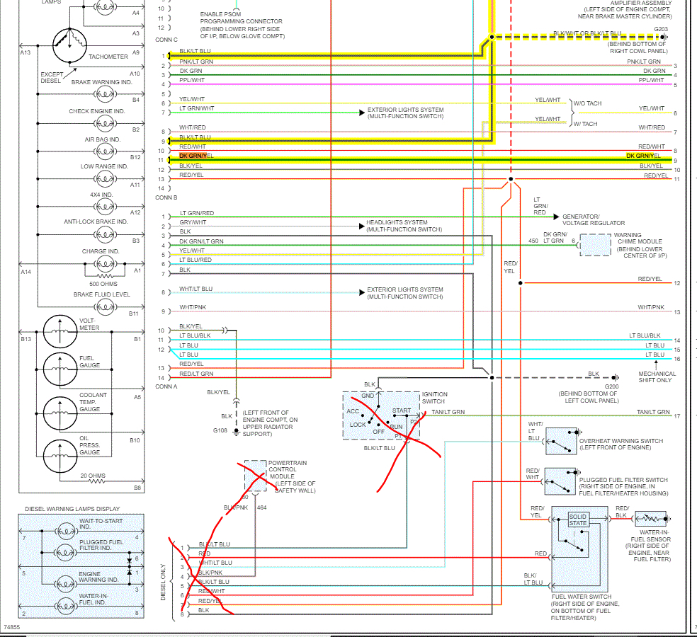
All other gauges work fine, as well as warning lights when I start the truck. I reviewed the wiring diagram in my Haynes manual, however it leaves a lot to be desired. I think I located the black wire with the light blue stripe and it is identified as a ground. Have not found what the green with yellow stripe wire is. Not sure about the accuracy of the diagram though. I will say, I checked all of the fuses related to any of the speed sensors, transmission controls, etc. And all fuses are fine. I cannot figure out what is wrong. I would appreciate some guidance. Thank you
Tuesday, November 30th, 2021 AT 11:22 AM

5 Replies

Tiny
JACOBANDNICKOLAS
  • MECHANIC
  • 108,300 POSTS
Hi,

After digging through several schematics, I believe I found it. The wiring you mentioned is part of the instrument cluster schematic.

Now, the black/light blue is a ground for the instrument panel and the green/yellow is related to the (if dark green/yellow) brake level sensor. If it is light green/yellow, it is a power supply to the instrument panel. Check fuse 8 in the interior fuse box.

I attached the schematics below that I found. I highlighted the wires involved. Take a look through them and let me know if they help. Note: There were two pages of schematics. I had to cut each in half to make them readable for you. I did overlap them so you can follow from one to the next.

These are the only wires I could find matching your description. Let me know your thoughts and hang in there. We'll get it figured out together. I did notice that the "Lt green/yellow wire does deal with the speedo. So make sure to check fuse 8. In addition to checking the fuse, make sure there is power to and from it.

Pic 1 below shows the fuse location. The remaining pics are schematics.

I hope this helps.

Take care,

Joe

See pics below.
Was this
answer
helpful?
Yes
No
Tuesday, November 30th, 2021 AT 8:31 PM
Tiny
JDPETERSON83
  • MEMBER
  • 5 POSTS
Thank you so much for the reply. After looking at this the absence of my digital odometer and the speedometer not working makes sense since the LG/yellow wire is the one that sparked when my drill bit hit it. Seeing that it goes to the speedometer/odometer module makes a lot of sense. I repaired the wires last night, and it still didn't work, but fuse #8 is not something I checked. My only other concern is why is my transmission shifting hard directly after this? It has never shifted hard and drove normally right before this happened. It cannot be coincidental. Looking at the schematics, I don't see anything in common with the wires going to the electronic shift control module other than the light blue wire (connector A12 for 4x4 indicator lamps in the instrument cluster) that ends up branching off of the 4x4 indicator switch, turning into a gray wire and a brown/white wire at the electronic shift control module. Would that electronic shift control module not working make the transmission shift hard?
Was this
answer
helpful?
Yes
No
Wednesday, December 1st, 2021 AT 7:24 AM
Tiny
JACOBANDNICKOLAS
  • MECHANIC
  • 108,300 POSTS
Actually, the vehicle speed sensor has a part in shifting. If the speedometer isn't working, that is my first suspect. The Vehicle Speed Sensor (VSS) generates a frequency signal input to the Powertrain Control Module (PCM) to control such parameters as fuel injection, ignition timing, transaxle shift scheduling, torque converter clutch scheduling, and vehicle speed. Check that fuse and let me know if it was bad. Also, make sure to confirm power to and from it. We may have a fuse fail that supplies power to the one in question.

Let me know what you find. I feel this is the issue but have been wrong before and will be again. LOL

Joe
Was this
answer
helpful?
Yes
No
Wednesday, December 1st, 2021 AT 5:59 PM
Tiny
JDPETERSON83
  • MEMBER
  • 5 POSTS
I checked the fuse in position 8 last night when I got home from work and sure enough, it was blown. I initially didn't check that fuse because of what it is listed as serving. Once I saw your wiring diagram and saw that the wire, I hit was constant hot power to the speedo module, I knew that had to be the issue. And you're right, after my research I came to the same conclusion. If the speedo module isn't getting power, then it can't send the signals it needs to from the VSS, the PCM or the TCM. The new fuse did the trick, and I made a permanent patch connection between all the damaged wires. Runs and drives like new. I appreciate your help sir!
Was this
answer
helpful?
Yes
No
Thursday, December 2nd, 2021 AT 7:28 AM
Tiny
JACOBANDNICKOLAS
  • MECHANIC
  • 108,300 POSTS
Hi,

First, you are very welcome, and thanks for the update. I'm glad to know you got it fixed. Components on today's vehicles depend on each other too much. LOL

Regardless, I'm glad it's fixed. Take good care of yourself, and please feel free to come back anytime in the future.

Joe
Was this
answer
helpful?
Yes
No
Thursday, December 2nd, 2021 AT 6:57 PM

Please login or register to post a reply.

Sponsored links