ECM wiring diagram needed?

Tiny
CSHAWNA016
  • MEMBER
  • 2008 PONTIAC G6
  • 2.4L
  • AUTOMATIC
  • 160,000 MILES
My family and I went on vacation. While we were gone someone cut some of the wires to my ECM connector below the pin. We just bought a new ECM, ECM connector and pins to replace the old one that had two pins burn up and everything was ready to connect. Now I don't know where the cut wires go if thrones in connector are correct or if someone moved them, I cannot find anywhere diagram of where each wire and pin go in connector and correct color for each whole help. I love my car it was almost finished and drivable.
Friday, July 21st, 2023 AT 7:28 AM

8 Replies

Tiny
AL514
  • MECHANIC
  • 4,111 POSTS
Hello, sorry to hear about your issue there. Thats a terrible thing for someone to do. Ill post the ECM connector pinout diagrams for you. You will have to by wire color to the correct pins. But you should be able to do it, just take your time, Ill post them in a few minutes.
Here are the 2 ECM connector pinouts. The pin number then the wire color, just so you know, the L-BU on pin 18 for example is Lite Blue. Make sure to check the fuses throughout the vehicle before attempting a start. If some wires were shorted out, there will be fuses burned up.
Which 2 pins burned up on the ECM connector?

https://www.2carpros.com/articles/how-to-check-a-car-fuse
Was this
answer
helpful?
Yes
No
-1
Saturday, July 22nd, 2023 AT 12:08 PM
Tiny
CSHAWNA016
  • MEMBER
  • 4 POSTS
Thank you very much. I believe one is red and white or possibly pink, white not sure if the color has faded the other is purple. Sending you picture of burned connector and the two wires. Greatly appreciate your help.
Was this
answer
helpful?
Yes
No
Saturday, July 22nd, 2023 AT 11:53 PM
Tiny
AL514
  • MECHANIC
  • 4,111 POSTS
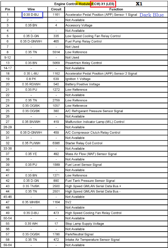
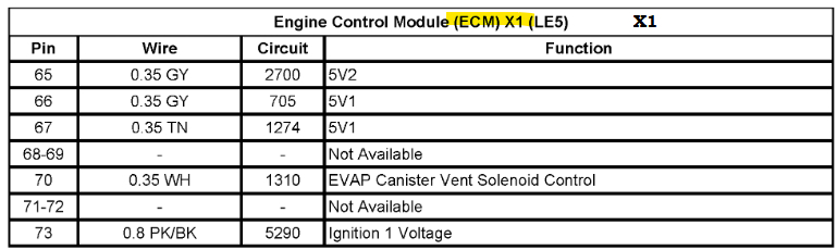
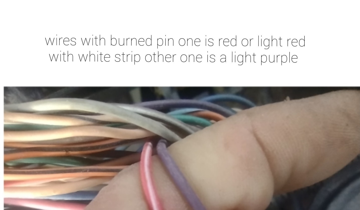
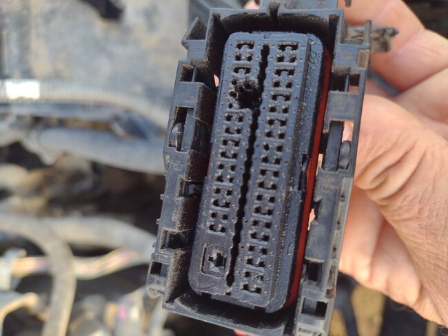
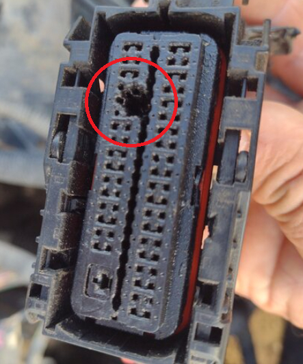
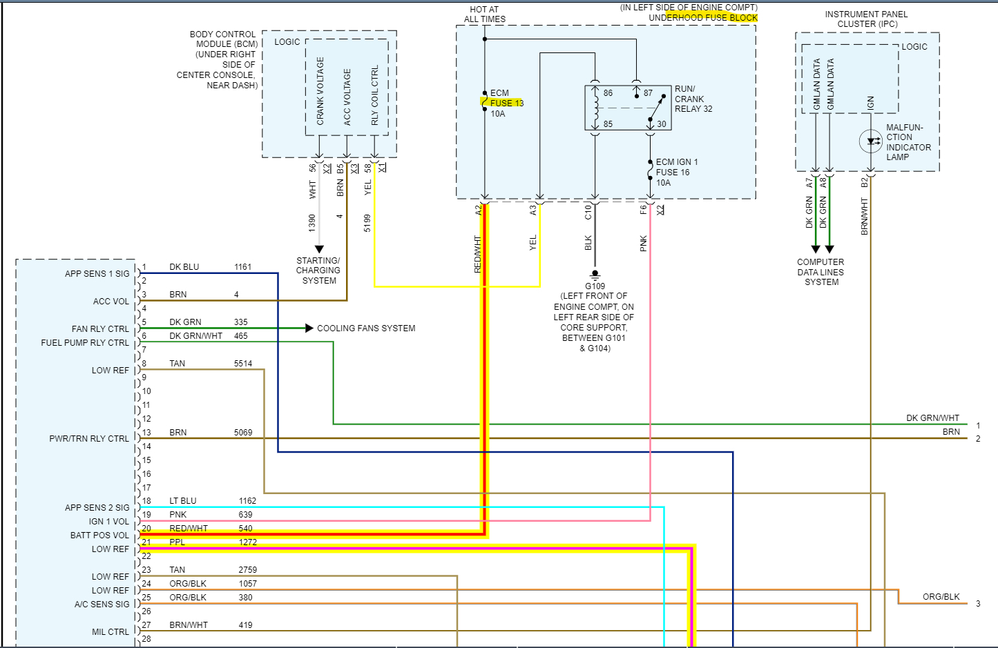
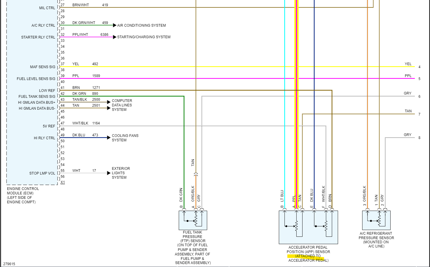
Okay, I'll try to figure out which wires those are. Looks pink/white and purple (violet). The issue with these PCM connectors is they are both Black and seem to have the same exact pin setup. Were you able to figure out which one is X1 and X2? And is this section of the connector missing? Looking through another service info location, there looks to be a couple different designs. This other site has the X1 connector with options LE5, LY7, LZ4, LZ9. The LY7 is def not yours, but is there a part number on the ECM case by chance? I do see different part number listings here, I'm not sure why service info is so different per site. But a part number would help. I think the difference might be engine size, but they have them listed kind of misleading.

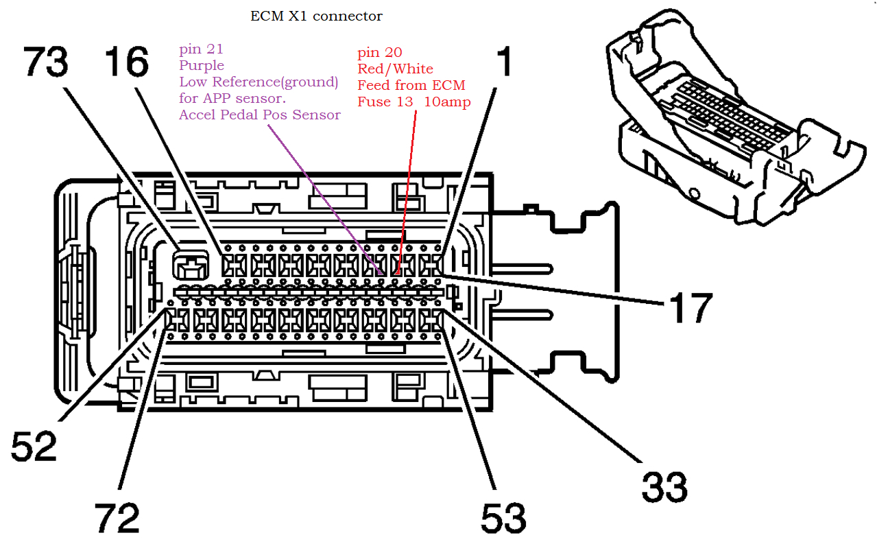
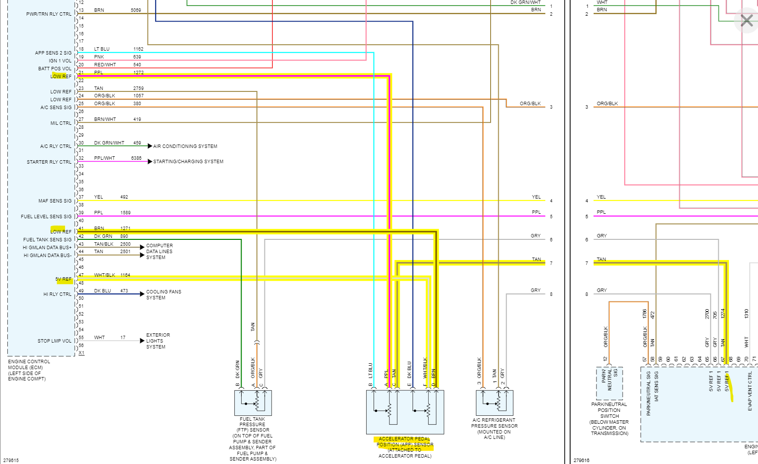
And are the 2 wires with the burned pins next to each other, I see a Red/White pin 20 Battery Positive voltage from ECM Fuse 13 10amp, and next to it pin 21 Purple Low Reference (Ground) for the APP sensor on the gas pedal. I don't see any Pink/White at all for the ECM. I can see if those 2 wires shorted together, especially if someone cut those wires together at the same time, because ECM Fuse 13 is hot at all times.

The APP sensor only works off of 5v references, not 12-volt. So, you may want to check the sensor on the gas pedal, it might be burned out as well, that fuse hopefully popped too.
Your ECM doesn't have 3 connectors, does it? Service info here is really incorrect in some places.
Ok I figured out the 3 connector ECM is for the 3.6liter engine, very misleading info here.
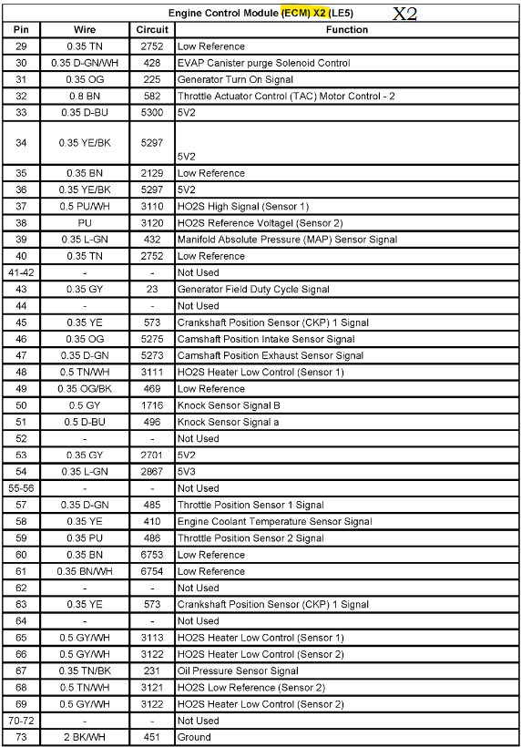
Diagram 4 is ECM X1 pins 20 and 21, for the wires you showed. Red/white 20, purple 21.
Was this
answer
helpful?
Yes
No
Sunday, July 23rd, 2023 AT 12:36 PM
Tiny
CSHAWNA016
  • MEMBER
  • 4 POSTS
There are only two connectors to the ECM and yes, the two burn pins are together and the part number for the ECM is 12612397 on the new ECM I bought o am sending pick if ECM I bought my car is the g6 base 2.4 if you need, I can send you the VIN. I know sometimes stuff goes by the VIN. Thank you for all your help.
Was this
answer
helpful?
Yes
No
Sunday, July 23rd, 2023 AT 5:12 PM
Tiny
AL514
  • MECHANIC
  • 4,111 POSTS
Okay, then yeah, it's the pins 20 and 21, so a battery feed could have been shorted through the APP sensor back to the ECM while the wires were being cut, I'm sure they used metal cutters for the wires which would short out a bunch of wires at once while they were doing it. Since it was a ground for the APP sensor the short might have gone through the APP sensor, then through the ECM to ground. Since that battery feed is a constant feed that is for the ECM memory. It needs a 12v feed that is very low current to sustain the EPROM and learned memory for the computer. So, check that ECM Fuse 13 10amp for a blown fuse.
This diagram is the APP sensor, it's basically 2 sensors in 1. It has two 5volt feeds, two Grounds (Low Reference) and two Signal wires, So 6 wires in total. If you unplug it, you can check the resistance across the 5v Ref wire and Low ref wire. They should both read about the same resistance. If 12volts were shorted through it on the Low Ref wire from pin 21, that would be the purple wire and the tan wire. The other two wires are the white/black and the brown. The 12-volts might have damaged the resistor you can see that is across the purple and tan wires. Since this is such a rare case, it's difficult to say exactly what happened. But that sensor is not made to handle 12-volts. You just want to make sure the sensor doesn't short out when you plug in the new ECM, it will cause a no start.
Was this
answer
helpful?
Yes
No
Sunday, July 23rd, 2023 AT 5:35 PM
Tiny
AL514
  • MECHANIC
  • 4,111 POSTS
If you are going to junk the present ECM, would you mind sending it to me, I'll see if I can repair any burned traces and send it back. I'll let you know right away if it's not repairable. But I repair modules on the side, along with a lot of other electronics. You'll have a spare if it's not too fried internally. There's no charge, just leave your email and Ill contact you on the side.
Was this
answer
helpful?
Yes
No
Monday, July 24th, 2023 AT 1:24 PM
Tiny
CSHAWNA016
  • MEMBER
  • 4 POSTS
My email is wayneshawna@gmail. Com
Was this
answer
helpful?
Yes
No
Tuesday, July 25th, 2023 AT 1:30 AM
Tiny
AL514
  • MECHANIC
  • 4,111 POSTS
Okay, did you have any trouble identifying the connectors to pins and wires so far? I see the connectors base on the new module look different colors, I believe they were both black in the wiring diagrams, but pretty sure those 2 burned pins were in X1. I don't see any pink/white or red/white wires in X2 at all. Just want to be sure everything is going back together okay.
Was this
answer
helpful?
Yes
No
Tuesday, July 25th, 2023 AT 12:38 PM

Please login or register to post a reply.

Sponsored links