Hi and thanks for using 2CarPros.
It sounds like the head gasket. The symptoms you described really seem to indicate it.
Here is a link that describes how to test for a bad head gasket:
https://www.2carpros.com/articles/head-gasket-blown-test
If you determine the head gasket is bad, here are the directions for cylinder head removal and replacement The attached pictures correlate with these directions and timing is included.
Cylinder Head, Removing and Installing
Special tools, testers and auxiliary items required
Wrench - Pin Type (3212)
Crankshaft Socket (T40058)
Crankshaft Locking Pin (T40069)
Camshaft Clamp (T40133)
Removing
The engine is installed.
The following information describes how to remove both cylinder heads at the same time.
If only one cylinder head will be removed, follow the applicable instructions in the following description.
ATTENTION!
There is a risk of injury because the fuel is under very high pressure.
Reduce the fuel pressure down to residual pressure before opening high pressure area of the fuel injection system.
- Reduce the fuel pressure in the high pressure area. Refer to => [ Before Opening High Pressure Fuel Injection System ] See: Fuel Delivery and Air Induction > Technician Safety Information > Before Opening High Pressure Fuel Injection System.
- Remove the upper coolant pipe. Refer to => [ Upper Coolant Pipes, Removing and Installing ] See: Coolant Line/Hose > Removal and Replacement > Upper Coolant Pipes, Removing and Installing.
- Remove the ribbed belt. Refer to => [ Ribbed Belt, Removing and Installing ] See: Drive Belt > Removal and Replacement > Ribbed Belt, Removing and Installing.
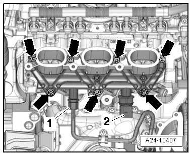
- Remove the intake manifold lower section. Refer to => [ Intake Manifold Lower Section with Fuel Rail, Removing and Installing ] See: Intake Manifold > Removal and Replacement > Intake Manifold Lower Section with Fuel Rail, Removing and Installing.
pic 1
- Disconnect the connectors on the fuel injectors.
- Remove the left and right timing chain covers. Refer to => [ Left and Right Timing Chain Cover, Removing and Installing ] See: Timing Cover > Removal and Replacement Left and Right Timing Chain Cover, Removing and Installing.
Vehicles without a secondary air injection system:
pic 2
- Remove the left front muffler. Refer to => [ Front Muffler, Removing and Installing ] See: Muffler > Removal and Replacement > Front Muffler, Removing and Installing.
- Remove the nuts - arrows - and the bolt - 1 -.
- Remove the left catalytic converter from the exhaust manifold and lay it aside.
The installation location is shown with the engine removed.
- Remove the right front muffler. Refer to => [ Front Muffler, Removing and Installing ] See: Muffler > Removal and Replacement > Front Muffler, Removing and Installing.
- Remove the nuts - arrows - and the bolt - 1 - and move the catalytic converter to the side.
pic 3
The installation location is shown with the engine removed.
Continuation for all vehicles:
pic 4
- Remove the bolts for the coolant pump ribbed belt pulley, using a Wrench - Pin Type (3212) to counterhold.
- Remove the bolts - 1 - and - 2 - and lay the power steering pump aside.
pic 5
The illustration shows the installation location on a vehicle with dynamic steering.
Ignore - item 3 - and - arrow -.
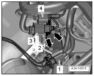
- Disconnect the connector - 3 - for the Engine Coolant Temperature Sensor (G62).
pic 6
- Remove the bolts - 1, 2, 4 and 5 - on the front coolant pipe.
Ignore the - arrows -.
- Remove the protective plate - 1 - for the high pressure line - arrows -.
pic 7
pic 8
ATTENTION!
There is a risk of injury because the fuel is under very high pressure.
Reduce the fuel pressure down to residual pressure before opening high pressure area of the fuel injection system.
To reduce remaining residual pressure, place clean cloth around the connector and carefully loosen connector.
- Reduce the fuel pressure in the high pressure area. Refer to => [ Before Opening High Pressure Fuel Injection System ] See: Fuel Delivery and Air Induction > Technician Safety Information > Before Opening High Pressure Fuel Injection System.
- Remove the threaded connection - 1 - and the union nuts - 2 - and - 3 -.
- Remove the bolts - arrows - on the retaining plates and the high pressure line.
- Remove the threaded connection - 2 - and move the fuel supply line to the side.
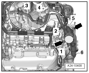
pic 8
- Disconnect the connectors - 1 - and - 6 -.
Ignore - items 3, 4 and 5 - and - arrow -.
- Disconnect the right and left electrical connectors - arrows - on the camshaft adjuster actuators.
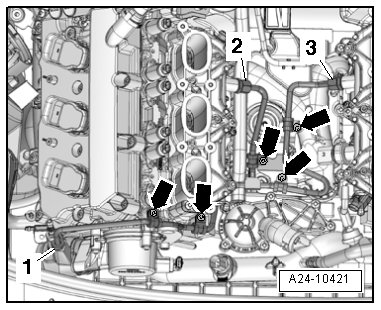
pic 9
- Remove the bolts - 1 - and - 2 - and free up the electrical wiring harness.
- Remove the cylinder head cover. For the left side. Refer to => [ Left Cylinder Head Cover, Removing and Installing ] See: Valve Cover > Removal and Replacement > Left Cylinder Head Cover, Removing and Installing and for the right side refer to => [ Right Cylinder Head Cover, Removing and Installing ] See: Valve Cover > Removal and Replacement > Right Cylinder Head Cover, Removing and Installing.
- Disconnect the connector - 3 - on the Camshaft Position Sensor (G40).
pic10
- Remove the ground cable bolt - 4 -.
Ignore - item 1, 2 and 5 -.
- Remove the left and right timing chain covers => [ Left and Right Timing Chain Cover, Removing and Installing ] See: Timing Cover > Removal and Replacement > Left and Right Timing Chain Cover, Removing and Installing.
- Remove the bolts - arrows - and the bracket for the left connectors.
pic 11
Ignore items - 1 and 4 -.
- Remove the bolts - arrows - and the bracket for the right connectors.
pic 12
Ignore items - 1 and 4 -.
- Remove the bolt - arrow - and remove the oil dipstick with the guide tube.
pic 13
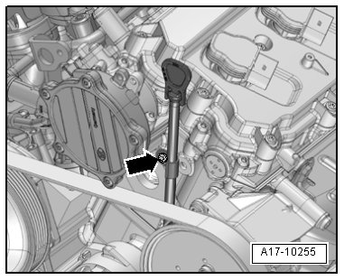
- Remove the vacuum hose from the vacuum pump - arrow - and free it up.
pic 14
- Remove the bolts - arrows - on the rear of the cylinder head.
pic 15
Left cylinder head: 3 bolts.
Right cylinder head: 4 bolts
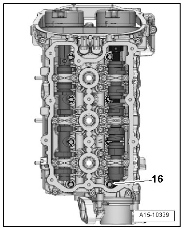
The cams on the intake camshaft partially restrict access to the cylinder head bolts, such as bolts - 1 - and - 2 - shown in this example.
oic 16
The slider on the camshaft must be pressed in the direction of - arrow A - using a plastic wedge to remove the bolt - 1 -.
The slider on the camshaft must be pressed in the direction of - arrow B - using a plastic wedge to remove the bolt - 2 -.
Risk of damage.
The camshaft slider must only slide in the base-circle phase, that is the rocker arm on the slider that will be moved must not be loaded with a cam. When loosening the cylinder head bolts, follow the sequence described in the following instruction.
There is a risk of it breaking.
The camshaft sliders must not slide on the thin ribs.
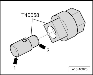
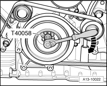
- Insert the Crankshaft Socket (T40058) guide pins as follows:
pic 17
The large diameter - arrow 1 - faces the engine.
The small diameter - arrow 2 - faces the adapter.
- Rotate the crankshaft in the direction of engine rotation - arrow - using the Crankshaft Socket (T40058) until the camshaft position shown in the following illustration is reached.
pic 18
The openings - arrows - on the exhaust camshafts must face toward the outer side of the engine as shown in the illustration.
pic 19
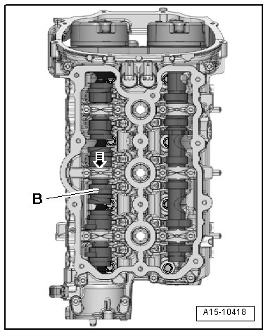
Left cylinder head:
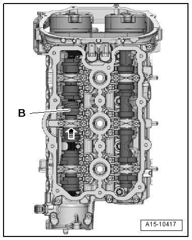
pic 20
- Slide the unloaded camshaft slider - B - as far as the stop in the direction of the - arrow -.
Right cylinder head:
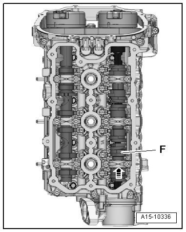
pic 21
- Slide the unloaded camshaft slider - F - as far as the stop in the direction of the - arrow -.
Continuation for both cylinder heads:
pic 22
- Turn the crankshaft one full revolution (360°) in the direction of engine rotation - arrow - using the Crankshaft Socket (T40058).
The threaded holes - arrows - in the camshafts must face upward.
pic 23
Left cylinder head:
pic 24
- Remove the bolt - 1 -.
Right cylinder head:
pic 25
- Remove the bolt - 2 -.
Continuation for both cylinder heads:
pic 26
- Turn the crankshaft one full revolution (360°) in the direction of engine rotation - arrow - using the Crankshaft Socket (T40058).
The openings - arrows - on the exhaust camshafts must face toward the outer side of the engine.
pic 27
Left cylinder head:
pic 28
- Slide the unloaded camshaft sliders - B - and - C - as far as the stop in the direction of the - arrow -.
Right cylinder head:
pic 29
- Slide the unloaded camshaft slider - F - as far as the stop in the direction of the - arrow -.
Continuation for both cylinder heads:
pic 30
- Turn the crankshaft one full revolution (360°) in the direction of engine rotation - arrow - using the Crankshaft Socket (T40058).
The threaded holes - arrows - in the camshafts must face upward.
pic 31
- Remove the camshaft timing chains from the camshafts. Refer to => [ Camshaft Timing Chain, Removing from Camshafts ] See: Timing Chain > Removal and Replacement > Camshaft Timing Chain, Removing from Camshafts.
Risk of damaging valves and piston crowns.
If the camshaft timing chain was also only removed on one cylinder head, the crankshaft must not be rotated any more.
Left cylinder head:
pic 32
- Remove the bolts - 3 through 9 - while sliding the unloaded camshaft slider - A - accordingly.
- Remove the cylinder head.
Right cylinder head:
pic 33
- Remove the bolts - 10 through 16 - while sliding the unloaded camshaft sliders - D - and - E - accordingly.
- Remove the cylinder head.
Installing
Tightening specifications. Refer to => [ Overview - Cylinder Head ] See: Cylinder Head Assembly > Removal and Replacement > Overview - Cylinder Head.
The sealing surfaces could be damaged.
Carefully remove sealant residue from cylinder head and cylinder block.
Make sure that no long scrapes or scratches result.
Risk of damaging cylinder block.
There must be no oil or coolant in the blind holes for the cylinder head bolts in the cylinder block.
Risk of cylinder head seal leaking.
Carefully remove all grinding and sanding residue.
Only unpack new cylinder head gasket immediately prior to installation.
To prevent cylinder head seal silicone layer and recessed area from being damaged, always handle seal extremely carefully.
Risk of damaging open valves.
If a replacement cylinder is installed, only remove plastic base right before cylinder head is installed to protect open valves.
Risk of damaging valves and piston heads after working on valve train.
To ensure valves do not strike pistons when starting, carefully rotate engine at least two full revolutions.
Replace the bolts which are being tightened with an additional turn.
Replace self-locking nuts, sealing rings, seals and O-rings.
Note different sealant for cylinder head sealing surfaces and bolts.
If a replacement cylinder is installed, the contact surfaces between the hydraulic adjusting elements, roller rocker levers and cam running surfaces must be lubricated before installing the cylinder head cover.
Secure all hose connections with hose clamps of the same type as those equipped by the factory. Refer to the Parts Catalog.
Change the coolant and engine oil whenever replacing the cylinder head or cylinder head seal.
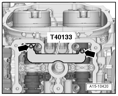
- Before installing the cylinder head, set the crankshaft and camshafts to "TDC" and install the Camshaft Clamp (T40133) on both cylinder heads and tighten to 25 Nm - arrows -.
pic 34
The Camshaft Clamp (T40133) is correctly positioned when the holes for the cylinder head bolts remain free.
Crankshaft Locking Pin (T40069) must be screwed into the crankshaft.
pic 35
- Set cylinder head gasket in place.
pic 36
Pay close attention to centering pins - arrows - in cylinder block.
Cylinder head gasket installation position: "open" (top) marking or part number toward cylinder head.
- Set the cylinder head in place.
Left cylinder head:
pic 37
- Insert the bolts - 1 through 7 - while sliding the unloaded camshaft slider - A - accordingly.
- Tighten the bolts in 3 steps following the sequence - 1 to 7 -. Refer to => [ Overview - Cylinder Head ] See: Cylinder Head Assembly > Removal and Replacement > Overview - Cylinder Head.
Right cylinder head:
pic 38
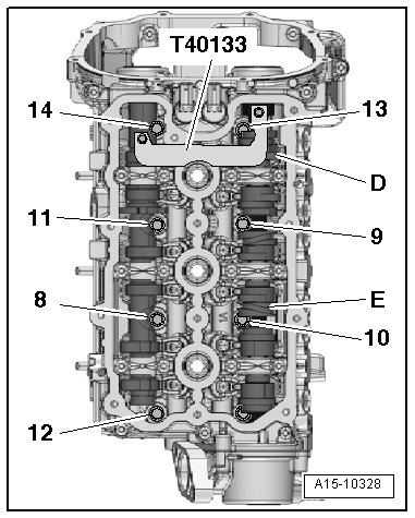
- Insert the bolts - 8 through 14 - while sliding the unloaded camshaft sliders - D - and - E - accordingly.
- Tighten the bolts in 3 steps following the sequence - 8 to 14 -. Refer to => [ Overview - Cylinder Head ] See: Cylinder Head Assembly > Removal and Replacement > Overview - Cylinder Head.
Continuation for both cylinder heads:
pic 39
- Position the camshaft timing chain on the camshafts. Refer to => [ ] See: Timing Chain > Removal and Replacement > Camshaft Timing Chain, Removing from Camshafts.
- Remove the Camshaft Clamp (T40133) and the Crankshaft Locking Pin (T40069).
- Turn the crankshaft one full revolution (360°) in the direction of engine rotation - arrow - using the Crankshaft Socket (T40058).
The openings - arrows - on the exhaust camshafts must face toward the outer side of the engine.
pic 40
Left cylinder head:
pic 41
- Slide the unloaded camshaft sliders - B - and - C - as far as the stop in the direction of the - arrow -.
Right cylinder head:
pic 42
- Slide the unloaded camshaft slider - F - as far as the stop in the direction of the - arrow -.
Continuation for both cylinder heads:
pic 43
- Turn the crankshaft one full revolution (360°) in the direction of engine rotation - arrow - using the Crankshaft Socket (T40058).
The threaded holes - arrows - in the camshafts must face upward.
pic 44
Left cylinder head:
pic 45
- Insert the bolt - 15 - and tighten it in 3 steps. Refer to => [ Overview - Cylinder Head ] See: Cylinder Head Assembly > Removal and Replacement > Overview - Cylinder Head.
Right cylinder head:
pic 46
- Insert the bolt - 16 - and tighten it in 3 steps. Refer to => [ Overview - Cylinder Head ] See: Cylinder Head Assembly > Removal and Replacement > Overview - Cylinder Head.
Continuation for both cylinder heads:
pic 47
- Turn the crankshaft one full revolution (360°) in the direction of engine rotation - arrow - using the Crankshaft Socket (T40058).
The openings - arrows - on the exhaust camshafts must face toward the outer side of the engine.
pic 48
Left cylinder head:
pic 49
- Slide the unloaded camshaft slider - B - as far as the stop in the direction of the - arrow -.
Right cylinder head:
pic 50
- Slide the unloaded camshaft slider - F - as far as the stop in the direction of the - arrow -.
Continuation for both cylinder heads:
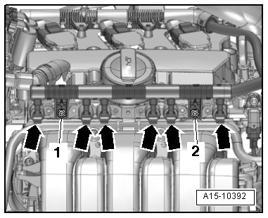
pic 51
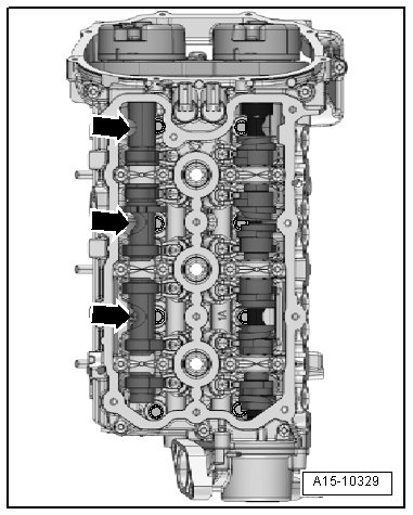
- Tighten the bolts - arrows -.
Left cylinder head: 3 bolts.
Right cylinder head: 4 bolts
Do not tighten cylinder head bolts after repairs.
Install in reverse order of removal. Note the following:
- Install oil dipstick guide tube. Refer to => [ Oil dipstick guide tube - tightening specifications ] See: Cylinder Head Assembly > Removal and Replacement > Overview - Cylinder Head.
- Position the camshaft timing chain on the camshafts. Refer to => [ ] See: Timing Chain > Removal and Replacement > Camshaft Timing Chain, Removing from Camshafts.
- Install the cylinder head cover. For the left side. Refer to => [ Left Cylinder Head Cover, Removing and Installing ] See: Valve Cover > Removal and Replacement > Left Cylinder Head Cover, Removing and Installing and for the right side refer to => [ Right Cylinder Head Cover, Removing and Installing ] See: Valve Cover > Removal and Replacement > Right Cylinder Head Cover, Removing and Installing.
- Install front coolant pipe. Refer to => [ Front Coolant Pipes, Removing and Installing ] See: Coolant Line/Hose > Removal and Replacement > Front Coolant Pipes, Removing and Installing.
- Install the power steering pump.
- Install the left catalytic converter: for vehicles with manual transmissions. Refer to => [ Left Catalytic Converter, Removing and Installing ] See: Catalytic Converter > Removal and Replacement > Left Catalytic Converter, Removing and Installing. For vehicles with the multitronic 0AW or automatic transmission 0B6. Refer to => [ Left Catalytic Converter, Removing and Installing ] See: Catalytic Converter > Removal and Replacement > Left Catalytic Converter, Removing and Installing.
- Install the right catalytic converter: for vehicles with manual transmissions/manual transmission 0AW. Refer to => [ Right Catalytic Converter, Removing and Installing ] See: Catalytic Converter > Removal and Replacement > Right Catalytic Converter, Removing and Installing. For vehicles with the automatic transmission 0B6 or automatic transmission 0B6. Refer to => [ Right Catalytic Converter, Removing and Installing ] See: Catalytic Converter > Removal and Replacement > Right Catalytic Converter, Removing and Installing.
- Install the front muffler. Refer to => [ Front Muffler, Removing and Installing ] See: Muffler > Removal and Replacement > Front Muffler, Removing and Installing.
- Install the plenum chamber bulkhead.
- Install the high pressure line, fuel supply line and the lower section of the intake manifold. Refer to [ Overview - Intake Manifold Lower Section with Fuel Rail ] See: Fuel Rail > Removal and Replacement Overview - Intake Manifold Lower Section with Fuel Rail.
- Install the ribbed belt. Refer to [ Ribbed Belt, Removing and Installing ] See: Drive Belt Removal and Replacement Ribbed Belt, Removing and Installing.
- Install the upper coolant pipe. Refer to [ Upper Coolant Pipes, Removing and Installing ] See: Coolant Line/Hose Removal and Replacement Upper Coolant Pipes, Removing and Installing.
- Change the engine oil.
- Replace the coolant. Refer to [ Coolant, Draining and Filling ] See: Cooling System Procedures Coolant, Draining and Filling.
______________________________
Timing
Camshaft Timing Chain, Removing and Installing
Removing
The transmission is removed.
- Remove the lower timing chain cover. Refer to [ Lower Timing Chain Cover, Removing and Installing ] See: Timing Cover > Removal and Replacement Lower Timing Chain Cover, Removing and Installing.
- Remove the camshaft timing chains from the camshafts. Refer to => [ Camshaft Timing Chain, Removing from Camshafts ] See: Timing Chain Removal and Replacement > Camshaft Timing Chain, Removing from Camshafts.
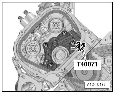
pic 52
If the running direction is reversed on a used camshaft timing chain, it could be damaged.
Paint arrows to mark the left and right camshaft timing chain running direction so they can be installed again. Do not mark camshaft timing chain with punch, notch or something similar.
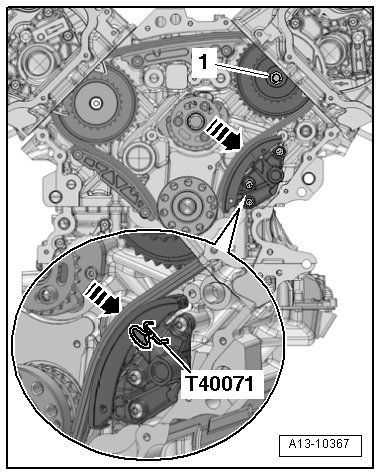
- Remove the Locking Pin (T40071) and the left camshaft timing chain.
- Remove the bolts - 1 - and - 2 - and the right chain tensioner.
pic 53
- Press the timing mechanism chain tensioner guide rail in the direction of the - arrow - and secure the chain tensioner using a Locking Pin (T40071).
pic 54
- Loosen the drive chain sprocket bolt - 1 - 1 turn.
- Tilt the drive chain sprocket with the mounting pins to the side slightly and remove the right camshaft timing chain upward.
Installing
Tightening specification. Refer to => [ Overview - Camshaft Timing Chains ] See: Timing Chain > Removal and Replacement > Overview - Camshaft Timing Chains.
If the tensioner was removed from the chain tensioner, then pay close attention to the installed position: the hole in the bottom of the housing faces the chain tensioner and the piston faces the tensioning rail.
Replace the bolts which are being tightened with an additional turn.
Risk of damaging valves and piston crowns.
If camshafts are rotated, crankshaft may not rest with any piston at "TDC".
- Position the left camshaft timing chain according to the markings made during removal as shown in the illustration.
pic 55
- Press the guide rail for the left camshaft timing chain tensioner down and secure the chain tensioner using a Locking Pin (T40071).
- Guide the right camshaft timing chain on the drive sprocket mounting pins while noting the markings made during removal.
pic 56
- Tighten the mounting pin bolts - 1 -.
- Remove the Locking Pin (T40071).
- Insert the chain tensioner at the right cylinder head and position the camshaft timing chain.
imageOpen In New TabZoom/Print
- Tighten the bolts - 1 - and - 2 -.
Install in reverse order of removal. Note the following:
- Position the camshaft timing chain on the camshafts. Refer to => [ ] See: Timing Chain > Removal and Replacement > Camshaft Timing Chain, Removing from Camshafts.
- Install the timing chain cover lower section. Refer to => [ Lower Timing Chain Cover, Removing and Installing ] See: Timing Cover > Removal and Replacement > Lower Timing Chain Cover, Removing and Installing.
- Fill the engine oil and check the oil level. Refer to => [ Engine Oil, Checking Level ] See: Engine Oil > Procedures > Engine Oil, Checking Level.
___________________________________________
Let me know if this helps.
Joe
Images (Click to make bigger)
SPONSORED LINKS
Monday, February 4th, 2019 AT 7:49 PM