Hi and welcome to 2CarPros.
It's under the dash in the heater vent module. I will provide the directions. However, I have to start at the beginning to work you to the heater core. Step one under heater core replacement is removing the heater vent module, which is the worst part.
____________________________________________________
Note: You should drain the coolant before starting this procedure.
First, you will need to remove the glove box and instrument panel. Next, the heater vent module needs removed. Here are the directions for removal and replacement of that component. The attached pictures correlate with these directions.
______________________________________________________
HEATER/VENT MODULE REPLACEMENT
Heater/Vent Module Replacement
picture 1
1. Remove the instrument panel. Refer to Instrument Panel Carrier Replacement See: Dashboard / Instrument Panel > Removal and Replacement.
2. Drain the engine coolant. Refer to Cooling System Draining and Filling See: Cooling System > Removal and Replacement.
3. On vehicles with automatic climate control only, cut the outer layer of the A/C evaporator and blower module in order to access the service access cover.
Picture 2
4. On vehicles with automatic climate control only, remove the service access cover mounting screws (1).
5. On vehicles with automatic climate control only, remove the service access cover (2).
6. On vehicles without automatic climate control, remove the blower motor resistor. Refer to Blower Motor Resistor Assembly Replacement See: Blower Motor > Procedures.
Important: Mark and use the same mounting bolt for the heater/vent module during the installation process. Other mounting bolts are longer and will obstruct the operation of the temperature door.
7. Remove the heat/vent module mounting bolt through the blower motor resistor or service access cover opening.
Picture 3
8. On vehicles with A/C only, remove the right wheel house panel. Refer to Wheelhouse Panel Replacement See: Front Fender Liner > Removal and Replacement.
9. On vehicles with A/C only, raise and support vehicle.
10. On vehicles with A/C only, remove the front right tire.
11. On the Utility only, remove the A/C evaporator and blower module heat shield screws.
12. On the Utility only, slide the A/C evaporator and blower module heat shield toward the front of the vehicle.
13. Remove the 2 lower heat/vent module mounting nuts.
14. On the Utility only, remove the A/C evaporator and blower module heat shield bracket.
15. Remove the bottom right heat/vent module mounting bolt from inside the vehicle.
Important: The heat/vent mounting stud has a flange on the inside and cannot be removed from under the hood. Stop turning the stud after the threads are off the heat/vent module.
16. On the Utility only, while an assistant inside the vehicle pulls the bottom right corner of the heat/vent module approximately 2.5 mm (1 in) back, remove the 2 heat/vent module mounting studs.
17. On vehicles with A/C only, lower the vehicle.
Picture 4
18. On vehicles with a 2.2 L engine only, remove the engine wiring harness bracket located at the rear of the intake manifold. Refer to Valve Rocker Arm Cover Replacement See: Valve Cover > Procedures.
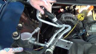
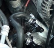
19. Remove the HVAC module mounting bolt located at the lower left side of the heater core to heater hose connection.
20. Remove the HVAC module mounting nut located at the lower right side of the heater core to heater connection.
Important: The heat/vent mounting stud has a flange on the inside and cannot be removed from under the hood. Stop turning the stud after the threads are off the heat/vent module.
21. On the Utility only, loosen the HVAC module mounting studs until the threads are free from the heat/vent module.
22. Disconnect all of the electrical connectors from the HVAC module.
23. Disconnect all of the vacuum lines from the heater assembly.
24. Disconnect the heater hoses from the heater core.
25. Remove the HVAC module from the vehicle.
Installation Procedure
picture 5
1. If replacing the HVAC module, transfer the components from the old heat/vent module as necessary.
Important: Before installing the HVAC module to the vehicle, ensure that the HVAC module mounting studs are located in the proper positions.
2. Install the HVAC module to the vehicle.
3. Connect the heater hoses to the heater core.
4. Connect all of the vacuum lines to the heater assembly.
5. Connect all of the electrical connectors to the HVAC module.
6. Install the bottom right HVAC module mounting bolt from inside the vehicle approximately halfway into the threads.
Notice: Use the correct fastener in the correct location. Replacement fasteners must be the correct part number for that application. Fasteners requiring replacement or fasteners requiring the use of thread locking compound or sealant are identified in the service procedure. Do not use paints, lubricants, or corrosion inhibitors on fasteners or fastener joint surfaces unless specified. These coatings affect fastener torque and joint clamping force and may damage the fastener. Use the correct tightening sequence and specifications when installing fasteners in order to avoid damage to parts and systems.
7. On the Utility only, install the HVAC module mounting stud located at the lower right side of the heater core to heater hoses connection in the engine compartment.
Tighten
Tighten the HVAC module mounting stud to 4.5 Nm (40 lb in).
8. On vehicles with A/C only, raise the vehicle.
9. On the Utility only, install the bottom right HVAC mounting studs. Ask an assistant to pull the bottom right corner of the HVAC module back from inside the vehicle.
Tighten
Tighten the heat/vent module mounting studs to 4.5 Nm (40 lb in).
10. On the Utility only, install the A/C evaporator and blower module heat shield bracket.
11. Install the heater/vent module mounting nuts.
Tighten
Tighten the HVAC module mounting nuts to 4.5 Nm (40 lb in).
12. On the Utility only, slide the A/C evaporator and blower module heat shield into the original position.
13. On the Utility only, install the A/C evaporator and blower module heat shield screws.
Tighten
Tighten the A/C evaporator and blower module heat shield screws 2.2 Nm (19 lb in).
Picture 6
14. On vehicles with A/C only, install the right front tire.
15. On vehicles with A/C only, lower the vehicle.
16. Install the bottom right HVAC module mounting bolt from inside the vehicle.
Tighten
Tighten the HVAC module mounting bolt to 4.5 Nm (40 lb in).
17. On vehicles with A/C only, install the right wheel house panel. Refer to Wheelhouse Panel Replacement in Body Front End See: Front Fender Liner > Removal and Replacement.
Picture 7
18. Install the HVAC module mounting nut located at the lower right side of the heater core to heater connection.
Tighten
Tighten the HVAC module mounting nut to 4.5 Nm (40 lb in).
19. Install the HVAC module mounting bolt located at the lower left side of the heater core to heater hose connection.
Tighten
Tighten the HVAC module mounting bolt to 4.5 Nm (40 lb in).
20. On vehicles with the 2.2 L engine only, install the engine wiring harness bracket located at the rear of the intake manifold. Refer to Valve Rocker Arm Cover Replacement See: Valve Cover > Procedures.
Important: Use the same mounting bolt marked during removal for the HVAC module during the installation process. Other mounting bolts are longer and will obstruct the operation of the temperature door.
21. Install the HVAC module mounting bolt through the blower motor resistor or service access cover opening.
Tighten
Tighten the HVAC module mounting bolt to 4.5 Nm (40 lb in).
22. On vehicles without automatic climate control, install the blower motor resistor. Refer to Blower Motor Resistor Assembly Replacement See: Blower Motor > Procedures.
Picture 8
23. On vehicles with automatic climate control only, install the service access cover (2).
24. On vehicles with automatic climate control only, install the service access cover mounting screws (1).
Tighten
Tighten the screws to 1.9 Nm (17 lb in).
Picture 9
25. On vehicles with automatic climate control only, install the outer layer of the A/C evaporator and blower module.
Important: Do not use RTV. Apply the adhesive bead as straight as possible. Allow the adhesive to set for 15 minutes or until the adhesive becomes tacky.
26. Seal the cut line using black weather-strip adhesive.
27. Refill the engine coolant. Refer to Cooling System Draining and Filling See: Cooling System > Removal and Replacement.
28. Install the instrument panel. Refer to Instrument Panel Carrier Replacement See: Dashboard / Instrument Panel > Removal and Replacement.
29. Calibrate the HVAC module actuator. Refer to Actuator Recalibration. See: Vehicle > Programming and Relearning
__________________________________________________
Now the directions specific to the heater core.
2001 Oldsmobile Truck Bravada V6-4.3L VIN W
Heater Core Replacement
Vehicle Heating and Air Conditioning Heater Core Service and Repair Procedures Heater Core Replacement
HEATER CORE REPLACEMENT
Heater Core Replacement
1. Remove the heater/vent module. Refer to Heater/Vent Module Replacement.
Picture 10
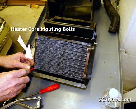
2. Remove the heater core access cover screws.
3. Remove the heater core access cover.
Picture 11
4. Remove the heater core from the heater/vent module.
Installation Procedure
picture 12
1. Install the heater core to the heater/vent module.
Picture 13
Notice: Use the correct fastener in the correct location. Replacement fasteners must be the correct part number for that application. Fasteners requiring replacement or fasteners requiring the use of thread locking compound or sealant are identified in the service procedure. Do not use paints, lubricants, or corrosion inhibitors on fasteners or fastener joint surfaces unless specified. These coatings affect fastener torque and joint clamping force and may damage the fastener. Use the correct tightening sequence and specifications when installing fasteners in order to avoid damage to parts and systems.
2. Install the heater core access cover.
Tighten
Tighten the heater core access cover screws to 1.9 Nm (17 lb in).
3. Install the heater/vent module. Refer to Heater/Vent Module Replacement.
____________________________________
I hope this helps. Let me know if you have other questions.
Take care,
Joe
Images (Click to make bigger)
Tuesday, March 12th, 2019 AT 7:39 PM