Backward! Bail out and save yourself!
Actually, nothing would be damaged. One is coming from the starter relay to put twelve volts onto the solenoid, "S" terminal. That one activates the solenoid to run the drive gear into the ring gear, then it switches on the high current to run the starter motor.
Your model year uses a breaker-point distributor. There is a ballast resistor in series with the ignition coil to limit current flow when the points are closed, and it makes the average voltage the coil sees around ten volts. During cranking, the starter draws the battery's voltage down to around ten volts. That is what is feeding the rest of the electrical system. When you start out with only ten volts, then drop some across the ballast resistor, the ignition coil will only see around six to eight volts. That will result in a very weak spark, and hard starting. To address that, the ballast resistor is bypassed only during cranking. That puts the full ten volts across the coil so it develops normal spark voltage.
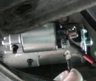
How that resistor is bypassed varies by manufacturer. Chrysler did it with a tap on the ignition switch. Ford did it with a second smaller terminal on their starter solenoids on the inner fender. GM did it with that second smaller terminal on the starter solenoid. When you turn the ignition switch to "crank", it turns on the starter relay. That relay sends twelve volts to the "S" terminal on the solenoid. The solenoid moves a metal plunger that pushes the drive gear to engage with the ring gear, then at the very end of its travel, a copper disc makes the contact between the large battery cable terminal and the large motor terminal, so the motor runs, and the second, smaller "R" terminal. "R" is for "relay". Now twelve volts shows up on that "R" terminal, (actually about ten volts), and that goes to the ignition coil, thereby bypassing the resistor.
If you switch the two smaller wires, when you turn the ignition switch to "crank", you will be putting full battery voltage onto the "R" terminal that has no connection inside the solenoid because it is not activated.
If you would prefer to not use trial and error, have a helper turn the ignition switch to "crank", then measure the voltages on the two wires. The one that has twelve volts goes to the "S" terminal on the solenoid.
SPONSORED LINKS
Tuesday, January 9th, 2018 AT 4:41 PM