Push Button Start MOD for jeeps

Tiny
CJ INPROGRESS
  • MEMBER
  • 1977 JEEP CJ5
  • 5.0L
  • V8
  • 4WD
  • MANUAL
  • 50,000 MILES
Good evening sir. First off, thank you for your service. I have read several of CJ Medvacs posts regarding a Push Button Start Mod for jeeps and am interested in doing the same for my for my vehicle. I do have a full service manual and am mechanically able provided detailed instruction and pictures. Wiring is not my first love when it comes to wrenching so I will research the heck out of something before diving in.

My vehicle is a manual, 304 non tilt steering wheel model. I would really like to complete the push button mod as I too am getting old and hate turning the key! I am interested in the non invasive setup you mentioned with the toggle switches, but am unsure of where to begin. I am not sure how to attach pictures but have a couple so you can see what I am working with. I am in no hurry.

Thank you kindly,
Brandon
Sunday, September 18th, 2016 AT 5:03 PM

47 Replies

Tiny
CJ MEDEVAC
  • MECHANIC
  • 11,004 POSTS
Great!

Thanks for the recognition!

My reasons for my mod were:

1) All CJ key switches (GM type) eventually the key falls out, being this was going be replace it #3 time, I figured it was time/ can fire it up with no key at all/ stranded when you drive somewhere without the key and accidentally turn it back to "lock"/ the theft possibility

2) The reach around and turn thing is just uncomfortable.

3) I hate keeping up with keys!

The other posts you saw, were my diagrams and pics of the task there, or was it just general discussing of what I had installed.

Mine's a 1977 w/ 258

Basically, I have two off/on safety covered toggles (one is all accessories, the other is ignition) and a two way momentary (flipping up or down will start the cranking). There is a hidden switch to kill it all!

I may go back and split off accessories like my cigarette lighter onto yet another safety toggle (presently there are two wires for accessories that I have hooked to the one toggle), this would let it stay hot when everything else is not. I would probably not use a lighted toggle. I just have to sit down and see what all is on the circuit.

Can you solder well?

I have most of the modification in pictures and diagrams, I do not mind sharing.

Picture one) How it looks on my dash, I may add a third safety toggle later.

Picture two ) Completed unit, modified ignition switch in my lower hand. My buddy could not believe I finished it and plugged it right in with no problems or no need to troubleshoot any mis-wiring.

Picture three) See! The original harness clips right in to the modified ignition switch and it can be totally removed and put back to the old way in a jiffy, if need be! (If you get another OEM ignition switch)

Picture four) "Mr. Jeep"

Picture five) A glimpse of my Man cave/ Guest room

This sort of what you are after?

Send a picture of your Jeep!

The Medic
Was this
answer
helpful?
Yes
No
Sunday, September 18th, 2016 AT 7:46 PM
Tiny
CJ MEDEVAC
  • MECHANIC
  • 11,004 POSTS
Wife just told me I made this sound like that was all I was going give you.

No no no no!

I have a bunch more for you - step by step!

Keep responding, especially that you are understanding how this whole deal works, it is more than just a push button.

Need to know if your rig must go through annual inspections?

Is this a daily driver?

The Medic
Was this
answer
helpful?
Yes
No
Sunday, September 18th, 2016 AT 8:35 PM
Tiny
CJ INPROGRESS
  • MEMBER
  • 26 POSTS
Yes sir! That is exactly how I would like to complete this mod. Very clean and reversible if need be. I live in rural Alabama so the need for vehicle inspections does not exist, which is fine with me!

This Jeep is not a daily driver, but I do get it out two or three days a week for exercise. I like the idea of not having to keep up with keys and am tired of wrestling with the ignition trying to get it to fire up.

As I mentioned before, I am capable of completing most anything mechanical as long as I have detailed instructions and pictures. I have had jeep for a couple years and am still learning my way around it.

Attached are a couple pictures.

Thanks
Was this
answer
helpful?
Yes
No
Monday, September 19th, 2016 AT 6:00 AM
Tiny
CJ INPROGRESS
  • MEMBER
  • 26 POSTS
Here are a couple more pictures to show you what I am dealing with. I guess these wires are going up to the ignition switch on top of the column.
Was this
answer
helpful?
Yes
No
Monday, September 19th, 2016 AT 6:29 AM
Tiny
CJ INPROGRESS
  • MEMBER
  • 26 POSTS
I believe the previous pictures are of the turn signal switch assembly. Apologize for the multiple replies.
Was this
answer
helpful?
Yes
No
Monday, September 19th, 2016 AT 6:32 AM
Tiny
CJ MEDEVAC
  • MECHANIC
  • 11,004 POSTS
So, you want it "my way" or do you want me to revamp it to include the 3rd toggle?

Correct- That is turn signal and horn harness

My pic shows the ign switch

Respond all you want! We love it!

I'm gonna give you a little at a time, this will let you ask questions or me elaborate (I hope you can understand my way of explaining stuff!)

This also gives me task/ goal to work on every evening for a CJ!

CJs are my thing and they are so good, few come on here to be fixed!

In the end, you can return to the beginning of this post to start the project!

It is very difficult to text stuff and not actually have hands on show it to ya!

Bear with me!

The Medic

1) I removed the turn signal connection, you can see the 2 connectors for the ign switch above it

2) Drivers side door to access switch

3) Free at last!
Was this
answer
helpful?
Yes
No
Monday, September 19th, 2016 AT 4:34 PM
Tiny
CJ INPROGRESS
  • MEMBER
  • 26 POSTS
I really like the way you did it as is. The ability to put back as stock fairly easy is pretty slick. The third toggle to me isn't very important.

I located the ignition switch no problem this afternoon. I didn't mention in my previous post, but I can solder.
Was this
answer
helpful?
Yes
No
Monday, September 19th, 2016 AT 5:18 PM
Tiny
CJ MEDEVAC
  • MECHANIC
  • 11,004 POSTS
Kinda going a little backwards for a minute

There is a "L" shaped rod that connects the key switch to the ignition switch.

Once the ign switch comes out, the rod is "Free"

But

More importantly

The Key switch can go in any position (if the lock cylinder is good, it will require the key) (if like mine had gotten, it would freely turn w/ no key)

So

Very Important!

I turned my empty (key-less) switch to "start", maybe even beyond "start"

I took some kinda stamped bi-fold door tool or bracket with hole big enough to go over the rod (anything similar will work)

I hooked the "L" on the rod and Large Hose Clamped the tool (it too was "L" shaped) to the lower steering column.

The bracket is merely an extension that got me to a clear spot on the column, away from the turn signal bracket

Thus stopping my key switch from moving at all (even if forced)

All the way past "start" keeps the mechanism as far away from the "Lock Position" as possible

I do not want the mechanism flopping about and Locking Up my steering at 55 MPH!

If your key still works correctly, it may have to stay in and turned to "start" (lock would be the only position to remove the key.) The key would do nothing.

'Course, if you left the rod loose (unlike mine) You could still lock the steering.

Really thinking about that though-NOT A GOOD IDEA!

You might start up and go with the push button, and be UNABLE to STEER because you FORGOT to unlock the steering with the key!

So

Lets keep it my way, steering will not lock at all, Key switch is unable to move at all. Driving is Safe!

Below is a pic of how I got the rod as low as possible and locked it off with the hose clamp. The "L" shaped rod is barely visible at the wires

See, I really try to think things out and make them child/ idiot proof!

Understand? Really 100%?

The Medic
Was this
answer
helpful?
Yes
No
Monday, September 19th, 2016 AT 7:33 PM
Tiny
CJ INPROGRESS
  • MEMBER
  • 26 POSTS
10-4. Understand this no problem. Actually got my full technical service manual out last night and was reviewing how all this was connected (By the way, I have a full 784 pg pdf version from 1977 if you are interested)

I was actually considering leaving the key in the ignition to keep everything unlocked AND leaving the original switch in place. Obviously, the key would serve no purpose other than allowing the steering wheel to stay unlocked.

I was thinking that I could procure a new switch to modify and then just plug it in to the existing harness.
Was this
answer
helpful?
Yes
No
Tuesday, September 20th, 2016 AT 6:21 AM
Tiny
CJ MEDEVAC
  • MECHANIC
  • 11,004 POSTS
Yes! Very Interested in the PDF (I'll get with you later on it)

Gonna show you a couple or 3 or more pics of what you are up against

Insure you have the straight column ignition switch (tilt is a mirror image of it) See link

http://shop.advanceautoparts.com/p/carquest-by-bwd-ignition-starter-switch-cs84/5971217-P?searchTerm=ignition+switch

I used heavy wire (12 gauge) on every thing except for things with low load (16 gauge). I probably went overboard, I figger better safe than sorry.

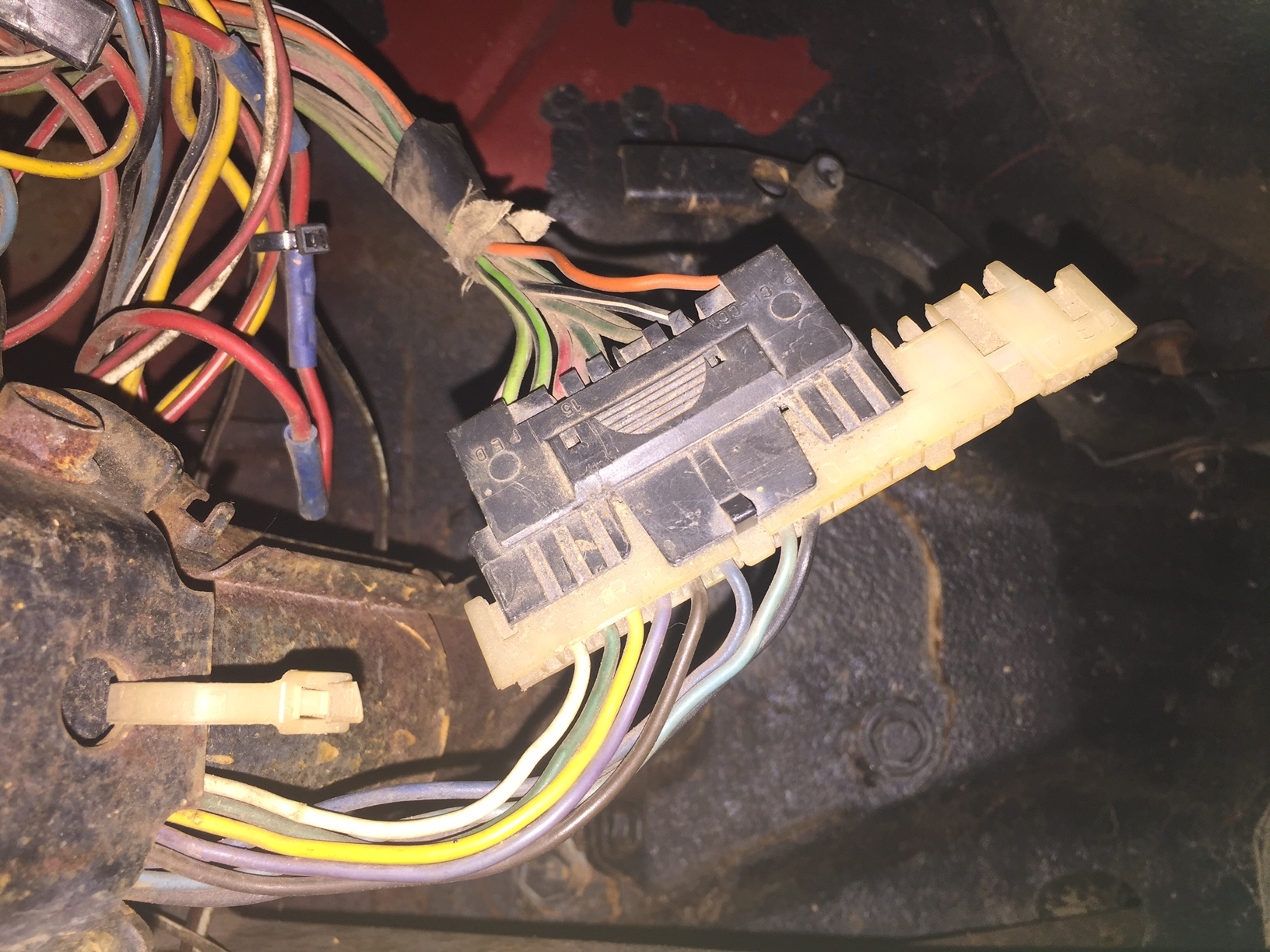
I contemplated just using female spade stake-ons and plugging each one into each of the two harness connectors, each female to it's correct position.

This then seemed like a bad idea!

Everything would sorta be backwards in its positions, not to mention being crunched up under the dash trying to figger out the positions, then later down the road one of them coming loose and leaving me searching for the problem.

The one BIG plug in is the best way to go!

You can use any kind of toggles you want

I got these two lighted safety toggles at Radio Shack for about $5 a pop

The momentary switch is spring loaded back to center ("off") and is momentary up or down, whichever way you approach it (starts either position). The one pictured is from Radio Shack, it was not heavy enough in amps (lasted a few weeks). I wound up getting a heavy one from an electrical supply house about $8 (I'll try to find out the amp rating for you). It has 6 male terminals (3 are for one side, 3 for the other)

One set of three are used for starting, the other three are used to verify the brake system is operational.

The original ign switch performs the "Brake test", You and I just didn't know it! While cranking, your brake light in the speedometer blinks real fast. If it does not, either your brake hydraulics may be malfunctioning or your bulb is blown! This test is also checked in places that require inspections.

The third toggle is an off/ on - strictly for security- kills everything- Sorta hid outta site. Also from Radio Shack.

I know!

I know!

We'll get to the good parts soon!

1) showing you the disassembled ign switch

2) This what we are gonna solder on- the opposite side from the male spades

3) Don't solder nuthin' yet! This sorta what it will eventually look like (I used my old one and had to clean it real good before I could solder). Wait till I get to the diagrams! I am using wire I had on hand, if you change colors, you will have to keep track of which color it takes the place of.

4) the goodies, less the aluminum angle iron mount

I have like 4-5 diagrams on how to wire it (my own drawings), it's been a good while, I UNDERSTAND THEM WELL, I wanna make sure I give you good diagrams that are fully understandable! I think they might impress you (they did me anyway! LOL!)

Your input so far?

'My a good teacher thus far?

The Medic

Was this
answer
helpful?
Yes
No
Tuesday, September 20th, 2016 AT 6:00 PM
Tiny
CJ INPROGRESS
  • MEMBER
  • 26 POSTS
This is excellent info and well presented.

I verified that I do in fact have the straight column ignition switch. Is the switch fairly easy to take apart? From the picture, it appears it just kind of "unsnaps"

I will get to work getting some toggle switches. Will this switch work for the momentary ?Says its rated for 20 amps.

https://www.amazon.com/Heavy-Handle-Momentary-Toggle-Switch/dp/B000LFVFA8/ref=pd_sim_sbs_263_1?ie=UTF8&psc=1&refRID=NKTC39P8XGTZSEJX05EE

Would it be OK to wire everything using 12 ga? or do I need to plan on getting some 16 ga wire as well? I'll probably try and mimic what you did just because it will be easier for me to trace my steps.

Interesting fact regarding the brake test. Had no idea this technology existed on these Jeeps esp in the 70's!

Pics are awesome and do a good job of helping me visualize everything. The manual I have is 118 mb, so when you are ready for it, I can dropbox it or would be happy to mail it to you on a CD. It's great for printing out a page or two to take out to the shop.
Was this
answer
helpful?
Yes
No
Tuesday, September 20th, 2016 AT 7:11 PM
Tiny
CJ MEDEVAC
  • MECHANIC
  • 11,004 POSTS
Yo Boss!

Letting you know I ain't forgot you!

Have a sick CJ about 8 miles away, They called me, hoping they wouldn't have to call the family in!

See you soon as I can!

The Medic
Was this
answer
helpful?
Yes
No
Wednesday, September 21st, 2016 AT 4:14 PM
Tiny
CJ INPROGRESS
  • MEMBER
  • 26 POSTS
No Problem! Sounds like they got the right man!
Was this
answer
helpful?
Yes
No
Wednesday, September 21st, 2016 AT 4:22 PM
Tiny
KEN L
  • MASTER CERTIFIED MECHANIC
  • 42,959 POSTS
Glad we could get it fixed please use 2CarPros. Com anytime we are here to help

Best, Ken
Was this
answer
helpful?
Yes
No
Thursday, September 22nd, 2016 AT 6:13 PM
Tiny
CJ MEDEVAC
  • MECHANIC
  • 11,004 POSTS
So this feller yesterday shelled out his T-5 tranny in his '85 or '86 CJ-7. He just didn't wanna accept that no magic could be performed last night to make it all better! I can see me getting drug all thru this! I've really been trying to get my '46 Willys ready for a paint job that is 20 years overdue! Between the wife and pals it's really hard.

I had to revamp my original computer drawings! Hard to read as I originally done 'em. Now that I talked the Wife out of the 46" Flat screen for my monitor ('course she got a 55" to take it's place) It's a lot EZer to see and use Microsoft Paint.

You can use piggy-backs on the the terminals to save room like I did or looking back on it,

It mighta been better if I had maybe just crimped 2 wires into the same connector, in those that share the same spade. That woulda cut down on a bunch of crap in the tight quarters.

Look my work over (best you can) I'm not as perfect as the females think I am! I looked it over 4 or 5 times after I got done.

When I soldered, I had a spray bottle of water to cool things off before I started melting thru to the other side.

Remember in this diagram, you are not soldering to the terminal the colored line is to! You are soldering to the other end of that terminal. (On the backside of the ign switch)

Let me know if you understand all of this.

Once you are good to go, on the deal, I'll show you the security switch, where and why I put it there.

Out of curiosity, what I did you go thru to find my push button mod?

I reckon Ken (the boss) thought we were done?

Am I good or what? LOL!

Your turn

The Medic
Was this
answer
helpful?
Yes
No
Thursday, September 22nd, 2016 AT 7:17 PM
Tiny
CJ MEDEVAC
  • MECHANIC
  • 11,004 POSTS
Pics are a no show?

Trying again

The Medic
Was this
answer
helpful?
Yes
No
Thursday, September 22nd, 2016 AT 7:22 PM
Tiny
CJ INPROGRESS
  • MEMBER
  • 26 POSTS
Once again, Great pics and info. I understand the wiring for the most part, but am still 15% ignorant when it comes to electric current, so bear with me.

Question 1: Is there a "top" or "bottom" or "left or right" to the momentary switch. I understand that the switch is basically split down the middle from top to bottom and that the "middle" poles feed from the ignition switch. I can't really tell from the pic which way the switch is laying. If its like the toggles in the pic, the "top of the switch should be to the far right. I've attached a (pic 1) that may help. Disregard the "left side" comment because obviously that would change depending on top or bottom. Was just trying to figure out which was top and which was bottom or if it even matters.

Question 2: The second toggle in the diagram appears to be wired a bit different in your actual harness(pic2). I made a note on the pic below of what I am talking about. Could be that it makes sense where it is, but with my limited knowledge, just want to make sure.

Question 3: Do you recommend 12ga wire for everything?

Question 4: I have not procured the new switch just yet. Any tips or tricks to dissembling it?

Got any pics of the '46 Willys? Would love to see em.

Thanks!
Was this
answer
helpful?
Yes
No
Friday, September 23rd, 2016 AT 6:15 AM
Tiny
CJ INPROGRESS
  • MEMBER
  • 26 POSTS
1st Pic didn't attach. Its the important one!
Was this
answer
helpful?
Yes
No
Friday, September 23rd, 2016 AT 6:16 AM
Tiny
CJ INPROGRESS
  • MEMBER
  • 26 POSTS
I've been studying hard and just wanted to make sure I am SURE about all this. Had another question regarding the ignition switch as well. It appears to me that the wiring diagram is showing a different pin to be soldered to for the brake failure feed when compared to the actual switch you show. I've attached a pic that may help. Disregard the "extra" yellow arrow in the far right of the pic. I forgot to delete. Apologize for peppering you with all these questions! Thank you in advance for your patience!
Was this
answer
helpful?
Yes
No
Friday, September 23rd, 2016 AT 7:02 AM
Tiny
CJ INPROGRESS
  • MEMBER
  • 26 POSTS
I think I just couldn't see the pin to solder to in the pic. Pretty positive you have it correct. Didnt mean to question your expertise!
Was this
answer
helpful?
Yes
No
Friday, September 23rd, 2016 AT 7:24 AM

Please login or register to post a reply.

Sponsored links