Hello
These are two separate problems. One is your right knock sensor located on the bottom right of the engine. The other is your catalytic converter.
I have give you the explanation of the codes. My suggestion. Replace both knock sensors. Mainly because you have to drain the anti freeze from the engine for one, so this is preventive maintenance, you are there, and they don't cost that much.
For the cat - after you change the knock sensors I would clear the codes and drive some more and see if you get the code P0420 again. Then we can talk more about cat replacement. But your O2 sensors are right by your cat also. We need to make sure that that is not going bad and your cat is.
Not sure where you pulled your codes at but you know you can go to Auto Zone or O'Reilly's and for free they can pull the codes to the car, and clear them. Most important. Once they check your codes, if they find something and you don't get it fixed and need to get back with us, please make sure you tell us exactly what the code was, number and all. Example, if the code was E0568 O2 Sensor bad. Then make sure you give us all of that. While there for free also they can bring their tester out and check your battery, alternator and starter.
The knock sensors detect abnormal vibration (spark knocking) in the engine. The sensors are mounted in the engine block near the cylinders. The knock sensors produce an AC voltage signal under all engine operating conditions. The PCM adjusts the Ignition Control (IC) spark timing based on the amplitude and frequency of the KS signal being received.
The PCM contains integrated Knock Sensor (KS) diagnostic circuitry. The PCM uses the circuitry to diagnose the KS sensors and related wiring. The PCM calculates an average voltage of each knock sensor's signals and takes instantaneous signal voltage readings. The PCM uses the instantaneous signal voltage readings to determine the state of the knock sensor circuitry. If the knock sensor system is operating normally, the PCM should monitor instantaneous KS signal voltage readings varying outside a voltage range above and below the calculated average voltage. If the PCM malfunctions in a manner which will not allow proper diagnosis of the KS circuit DTC P0325 will set. DTCs P0327 and P0332 are designed to diagnose the knock sensors, and related wiring, so problems encountered with the KS system should set a DTC.
Varying octane levels in today's gasoline may cause detonation in some engines. Detonation is caused by an uncontrolled explosion (burn) in the combustion chamber. This uncontrolled explosion could produce a flame front opposite that of the normal flame front produced by the spark plug. The rattling sound normally associated with detonation is the result of two or more opposing pressures (flame fronts) colliding within the combustion chamber. Though light detonation is sometimes considered normal, heavy detonation could result in engine damage. To control spark knock, a Knock Sensor (KS) system is used. This system is designed to retard spark timing when spark knock is detected in the engine. The KS system allows the engine to use maximum spark advance for optimal driveability and fuel economy.
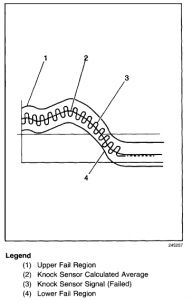
The PCM contains integrated Knock Sensor (KS) Diagnostic Circuitry. Input signals from the knock sensors are used to detect engine detonation, allowing the PCM to retard Ignition Control (IC) spark timing based on the amplitude and frequency of the KS signal being received. The knock sensors produce an AC signal under all engine operating conditions. The PCM calculates an average voltage of each knock sensor's signal and takes instantaneous signal voltage readings. The PCM uses the instantaneous signal voltage readings to determine the state of the knock sensor circuitry. If the knock sensor system is operating normally, the PCM should monitor instantaneous KS signal voltage readings varying outside a voltage range above and below the calculated average voltage (as shown in the normal knock sensor figure). If the PCM detects a knock sensor signal voltage within the calculated average voltage range, DTC P0327 or P0332 will set (as shown in the abnormal knock sensor figure).
REMOVAL PROCEDURE
Drain the cooling system.
Disconnect the wiring harness connector from the appropriate knock sensor.
Remove the knock sensor from engine block.
INSTALLATION PROCEDURE
IMPORTANT: Do Not apply thread sealant to sensor threads. Sensor is coated at the factory and applying additional sealant will affect the sensors ability to detect detonation.
NOTE: Refer to Fastener Notice in Service Precautions.
Hand start the knock sensor into the engine block. Tighten Tighten the knock sensor to 19 N.m (14 lb ft) .
Connect the wiring harness connector to the appropriate knock sensor.
Fill the cooling system.
Left sensor location In the bottom left side of the engine block
Right sensor location In the bottom right side of the engine block
Cat System
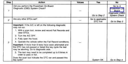
The numbers below refer to the step numbers on the diagnostic table:
The powertrain OBD system check prompts the technician to complete some basic tests and store the freeze frame and failure records data on the scan tool if applicable.
If any other DTCs are set, diagnose those DTCs first. A fault in a component can cause the converter to appear degraded or may have caused its failure.
Clearing the DTCs allows the catalyst test to be attempted 18 times and completed up to 6 times this key cycle. If the A/C is ON the diagnostic may not run. The engine must be warmed-up. The converter needs to be warmed-up by raising the engine speed more than idle for the specified time prior to each attempted test. Check and see if DTC passed or failed this key cycle. If the DTC does not pass or fail look for a possible reason that would cause the test to abort.
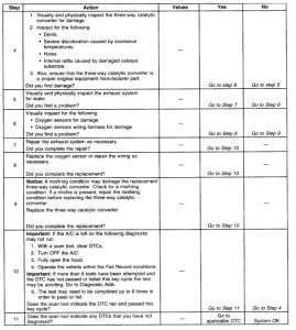
This step includes tests for conditions that can cause the three-way converter to appear degraded. Repair any problems found before proceeding with this table.
If the three-way converter needs to be replaced, make sure that another condition is not present which could damage the converter. These conditions may include: misfire, high engine oil or coolant consumption, retarded spark timing, weak spark or a plugged/leaking injectors. Correct any possible causes of converter damage before replacing the converter.
Nov 1, 2008 at 1:31 PM