You did not say what you're trying to solve. The instructor I used to work with made his students memorize sensor values because he never was a mechanic and only knew how to teach out of the text book. In practice, professionals only rarely measure the resistance of a sensor to verify what the Engine Computer already told them through a diagnostic fault code. If you think you're going to solve a problem by testing sensors, you are going to be at this for days. No customer would put up with being charged for that much time.
I can help with a few generic values but I do not think they will be of much use to you. Also, you might have the "throttle-by-wire" system so some of my values might be way off, particularly for the throttle position sensor.
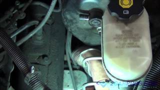
The common throttle position sensor used since the 1980's typically measures around 5,000 ohms from the ground terminal to the 5.0 volt feed terminal, but the actual value is meaningless. They don't operate according to resistance. They develop a signal voltage relative to their position. That means at half throttle there will be 2.5 volts on the signal wire. That will be true whether the resistance is 5,000 ohms, 10,000 ohms, 80 ohms, or any other value. The only thing you might find with a resistance reading is if the sensor is open, but even then, you'd already have had a fault code telling you that. There can also be an intermittent open circuit between the movable wiper and the resistor element due to a speck of broken-off carbon from that element. You'll never see that with a resistance reading, but if it lasts long enough, the computer will detect that for you and set a code. If you really want to test something of value, measure the voltage on the signal wire. You will see the voltage go smoothly from around 0.5 volts at idle to around 4.5 volts at wide-open-throttle. The only way you can possibly get that range of voltage is if the 5.0 volt feed and the ground circuits are both good, so there's no need to waste time looking at those.
There is one more potential problem. That is a break in the signal wire between the sensor and the computer. Your meter is measuring at the sensor. If you use a scanner to view the live data the computer sees, you will see the same voltage right at the computer. Work the accelerator pedal from idle to wide-open-throttle and you'll see the voltage change from 0.5 to 4.5 volts. That three-second test with a scanner, and no related fault code, is all that's needed to know that sensor is okay.
For temperature sensors, there are charts in the service manual and in text books, but those are only for explaining theory of operation. No professional has ever memorized those values, (except the poor unfortunate students of my former coworker). For the typical coolant temperature sensor, again, the actual resistance is meaningless. They cause extremely little trouble so if you are getting a fault code related to it, it is much more likely it was unplugged recently while the ignition switch was on, or there is a wiring problem or a corroded or stretched connector terminal. You might find a resistance reading of, lets say, 2,000 ohms, but only at a certain temperature. As the temperature goes up, its resistance goes down. You can watch this on a digital voltmeter or on a scanner, but on most systems there's an unexpected "glitch"' if you watch long enough. For all of these descriptions my values are approximate and are only for explaining how the systems work, so do not get excited if you find something different.
You will need to watch the voltage, not the resistance, for this observation. Also, any temperature sensor for the Engine Computer will have two wires, not one like on those used for dash gauges. If you find 0.2 volts, or close to 0 volts, you're on the ground wire. The other one is the signal wire. With a cold engine on a 60 degree F. Day, expect to find somewhere around 4.0 volts, ... Maybe even 3.5 volts. What's important is the voltage will drop as the sensor's resistance drops as its temperature goes up, but here is where that glitch comes into play. The voltage will drop to around 2.0 volts by the time the temperature gets to 160 degrees F, then it will suddenly jump up to 4.0 volts, then resume dropping again. This is because the computer has switched in a different series resistor to increase the accuracy of the readings. Below about 160 degrees, actual temperature is way too low to be of interest other than it is indeed rising. Normal operating temperature is 195 degrees F, and it's around those temperatures where high accuracy is needed. Once you see the signal voltage pop back up, it will continue dropping just like it did at first.
Besides an open circuit, the computer compares the coolant temperature sensor's readings to the intake air temperature sensor and / or battery temperature sensor to learn the characteristics of a new sensor, and to tell when one is sending an incorrect voltage. For example, if the engine has been off for more than six hours, all of those sensors had better be reading the same temperature.
Older two-wire crankshaft position sensors and camshaft position sensors were a coil of wire wrapped around a magnet. All you care about with those is there is not an open circuit. They aren't going to short and their resistance is not going to change. A typical reading might be 800 ohms, but you're just as likely to find 300 to 1500 ohms. As long as there is continuity, it's going to generate a voltage pulse when something moves past it to interrupt the magnetic field. The computer doesn't care what the voltage of those pulses are. The pulses are used for timing the initiation of an event, like firing an ignition coil or injector.
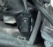
Newer crank and cam sensors are a three-wire design. They have a ground wire, a feed wire, and a signal wire. The feed voltage can be 5.0, 8.0, or 10 volts. I do not recall ever seeing one fed with 12 volts. Don't bother trying to learn anything of value with resistance readings on these. There's a bunch of circuitry inside that cannot be measured. We troubleshoot these base on symptoms. They do not always have time to set a fault code when they fail, because a failure results in a stalled engine, and the computer knows there should not be signals coming from them when the engine isn't rotating. The easiest way to know if a signal is missing is to view them on a scanner. Both sensors will be listed with a "No" or "Present", or something like that to indicate whether the signals are showing up at the computer.
You really cannot measure the signal voltages for these sensors either. They are a square wave that pulses between close to 0.0 volts and 5.0 volts. Digital voltmeters are designed to read a sine wave at 60 hertz. They are very inaccurate at any other frequency. Perhaps where you are that might be 50 hertz, but it's the same idea. If you have a meter that measures frequency, you might get a reading, but that wont tell you if the signal voltage is strong enough to be seen by the computer. You're better off observing if the computer is turning things on in response to the presence of those signals. Most commonly that is the electric fuel pump and voltage to the ignition coil and injectors. On Chrysler products, for example, all of those systems get voltage from the automatic shutdown (ASD) relay. One simple test for voltage at the ignition coil, during cranking, will tell you if that relay is turning on, and if it is, both sensors are working. Another three-second test and you can move on.
There is no way to test an oxygen sensor other than by watching it on a scanner. Even then, all you can do is verify it is switching between "rich" and "lean". The computer will set a fault code to tell you if that switching isn't occurring fast enough. The signal voltage most of them develop varies between around 0.2 to 0.8 volts, but they switch around two times per second. That is much too fast for a digital meter to display. Even if it could, the readings would change too quickly for you to see.
By "cylinder pressure" I am guessing you're doing a compression test. All we care about is all the cylinders are close to equal. One low cylinder could indicate a problem that needs to be diagnosed, but you aren't going to have a problem with all the cylinders at once unless valve timing is off. For that, compression will be real low and you will have to check the timing belt or chain.
Cooling systems are limited to 15 psi. For every pound of pressure, the boiling point of water is raised three degrees F. At 15 pounds, that raises the boiling point from 212 degrees to 257 degrees. You do not have to pressurize the system to 15 pounds to test for leaks. If it's a slow leak, there's dye for finding those that works much better than searching for an elusive wet spot.
As for measuring the resistance of ignition coils and injectors, you can find those values in the service manual, but interestingly, you will find just as many of them that are operating just fine and their resistances would say they are bad. Some injectors have around 12 ohms, and your meter leads can add another three or four ohms which would make a good injector look bad. Way too often I read where someone replaced a part because its resistance was not what some book said it should be, and they still have the same problem. If a mechanic diagnosed problems that way, he would be selling people a bucket-full of unneeded parts, or his shelves would be full of parts he may never be able to sell.
SPONSORED LINKS
Tuesday, August 16th, 2016 AT 3:26 AM