22 - Coolant sensor voltage low.
24 - Throttle position sensor voltage high/low.
37 - Part throttle unlock (PTU) circuit, open or short detected
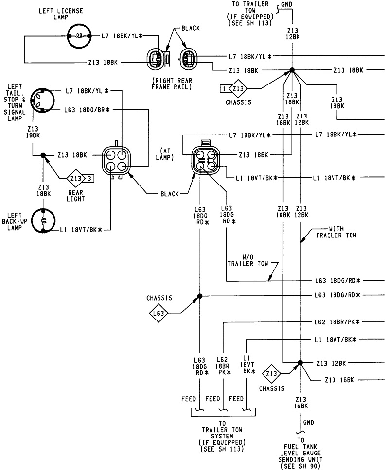
The wires likely are in the same harness that runs from the body to the engine, but their circuits aren't exactly related. The coolant temperature sensor circuit is shown in the first diagram. The throttle position sensor circuit is shown in the third diagram, but the wires start in the second diagram, so I included that one too.
Both sensor circuits are fed with a carefully regulated 5.0-volt supply from the Engine Computer, but they leave on different terminals. The CTS simply draws the voltage down on that line to form the signal voltage. Its sensing circuitry is inside the computer. The TPS 5.0 volts leaves the computer from terminal # 6, but note that line feeds multiple sensors. It feeds the MAP sensor and the crankshaft position sensor. If the engine runs, the crankshaft position sensor has to be working, so we know that 5.0-volt supply has to be okay.
What I would recommend for now is to treat this as two totally different problems and lets concentrate on just the CTS. That is the simplest circuit, and we may find the cause of both problems when we find the first one. The sensor itself is the last thing to suspect. Failures of temperature sensors are very low because there's just one part inside them. By far most problems are caused by a break in the wire, either the wire itself or between a pair of mating terminals in the connector. The resulting "open circuit" would cause the voltage on the tan / black wire to jump up to 5.0 volts. For the majority of sensors that are fed with five volts and ground, there are electrical or mechanical stops that limit their range of signal voltages to 0.5 to 4.5 volts, give or take a little. It's any signal voltage outside that range that gets detected as a defect and sets a fault code.
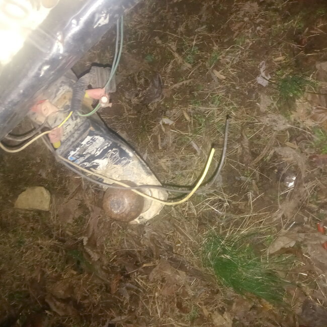
To get fault code 22, the tan / black wire is likely grounded someplace. First look at the wiring harness running to the engine to see if it has fallen down and is rubbing on the sharp edge of a metal bracket. Another place to look is if that harness runs on top of the inner fender or along the firewall and slides back and forth as the engine rocks. If you don't find anything, we're going to have to do a continuity or voltage test. If I remember correctly, that voltage should jump back up as soon as a short is removed.
When the other 5.0-volt supply for the TPS is shorted to ground, the computer shuts it down to protect it. First that short must be removed, then the ignition switch must be turned off, then back on to reset it.
The problem with TPS fault codes on '95 and older models is they don't specify if the signal voltage has gone to 0.0 volts or to 5.0 volts. Both are outside the acceptable range of 0.5 to 4.5 volts and will set the code. You'll have to take a voltage reading to see what the signal voltage is that set the code. I'm hoping you're going to find a spot where the harness is rubbed through causing two wires to short to ground. The clue here is you'll get that code if either the 5.0-volt supply wire or the TPS signal wire is grounded, but if it was the 5.0-volt supply wire, you'd get a similar fault code for the MAP sensor, and the engine wouldn't run with the 5.0 volts missing to the crankshaft position sensor. If we assume the 5.0-volt supply wire is okay, you can only get this TPS code if the signal wire is grounded, if there's a broken connection between the two mating terminals for the 5.0-volt line at the TPS connector, or if there's a break in either wire. There's more to the story with the TPS signal wire. That's why we have to know the voltage on its signal wire to know which defects to look for.
Also be aware that with both of these sensors, it is absolutely necessary they be plugged in when you take any voltage readings, otherwise they will have no meaning. You'll need to back-probe through their rubber weather seals alongside the wires.
If you need help using a digital voltmeter, check out this article first:
https://www.2carpros.com/articles/how-to-use-a-voltmeter
They're using an "auto-ranging" meter here. That's an expensive feature you don't need. You can find a perfectly fine meter at Harbor Freight Tools for around $7.00. Also look at Walmart, any hardware store, or any auto parts store. I can help you set it up if necessary.
If you haven't found a grounded wire by now, start by measuring the voltage on the tan / black wire at the coolant temperature sensor. The ignition switch must be in "run". If you find close to 0.0 volts, as the fault code has indicated, unplug the connector and recheck on that wire. I'm going to say it will stay at 0.0 volts, but in the very unlikely event I'm wrong, we'll have to look at the sensor for damage causing both wires to touch. I'm suspecting that tan / black wire is grounded long before it gets to the sensor's plug, so unplugging it isn't going to change anything. If you do find 0.0 volts, you should be able to monitor that voltage while you wiggle and move wire harnesses around. If you do something to momentarily remove the short, the voltage on that wire will jump up to 5.0 volts if the connector is unplugged, or to something between 0.5 and 4.5 volts if the connector is plugged in. A typical signal voltage is in the area of 2.5 volts, give or take a volt, at around 60 degrees.
Let me know what you find, then we'll figure out where to go next.
Images (Click to make bigger)
SPONSORED LINKS
Thursday, December 1st, 2022 AT 2:52 PM